Tracked vehicles (using slidenodes)
Intro
This is a step-by-step tutorial of how to make tracks for crawler crane/excavator/bulldozer/other heavy machines without suspension.
This page assumes knowledge softbody basics: basic N/B, rotators, submeshing and slidenodes.
Your brain also has a naturally built-in physics simulator. Try to use it when you build the tracks. Look at your structure, imagine the nodes moving around as they would do in RoR, and try to see if your structure will work. It's not hard.
NOTES about the pictures:
- the SketchUp models are only to show the structure in 3D, you CAN NOT make working N/B track in SketchUp.
- models show very few beams just to make it easier to see the basic structure.
Of course the actual N/B structure shall have more beams to make it stronger.
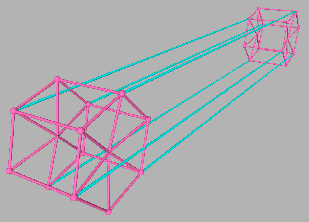
Step 1: Making the frame
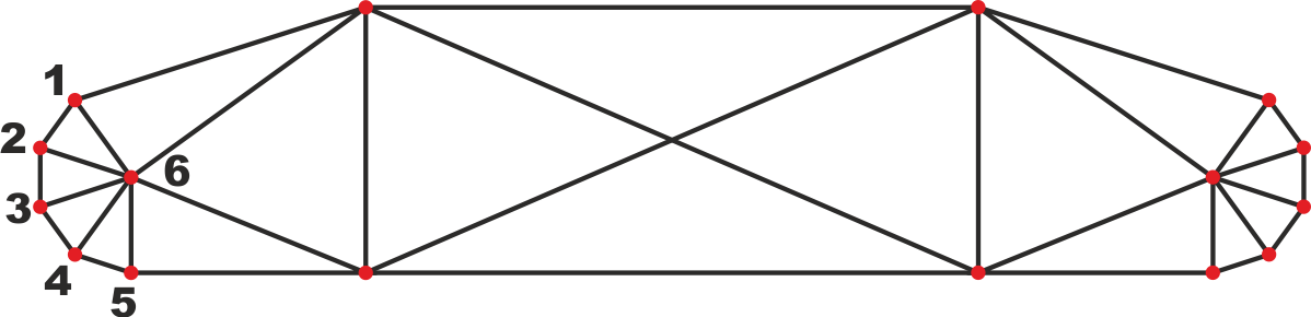
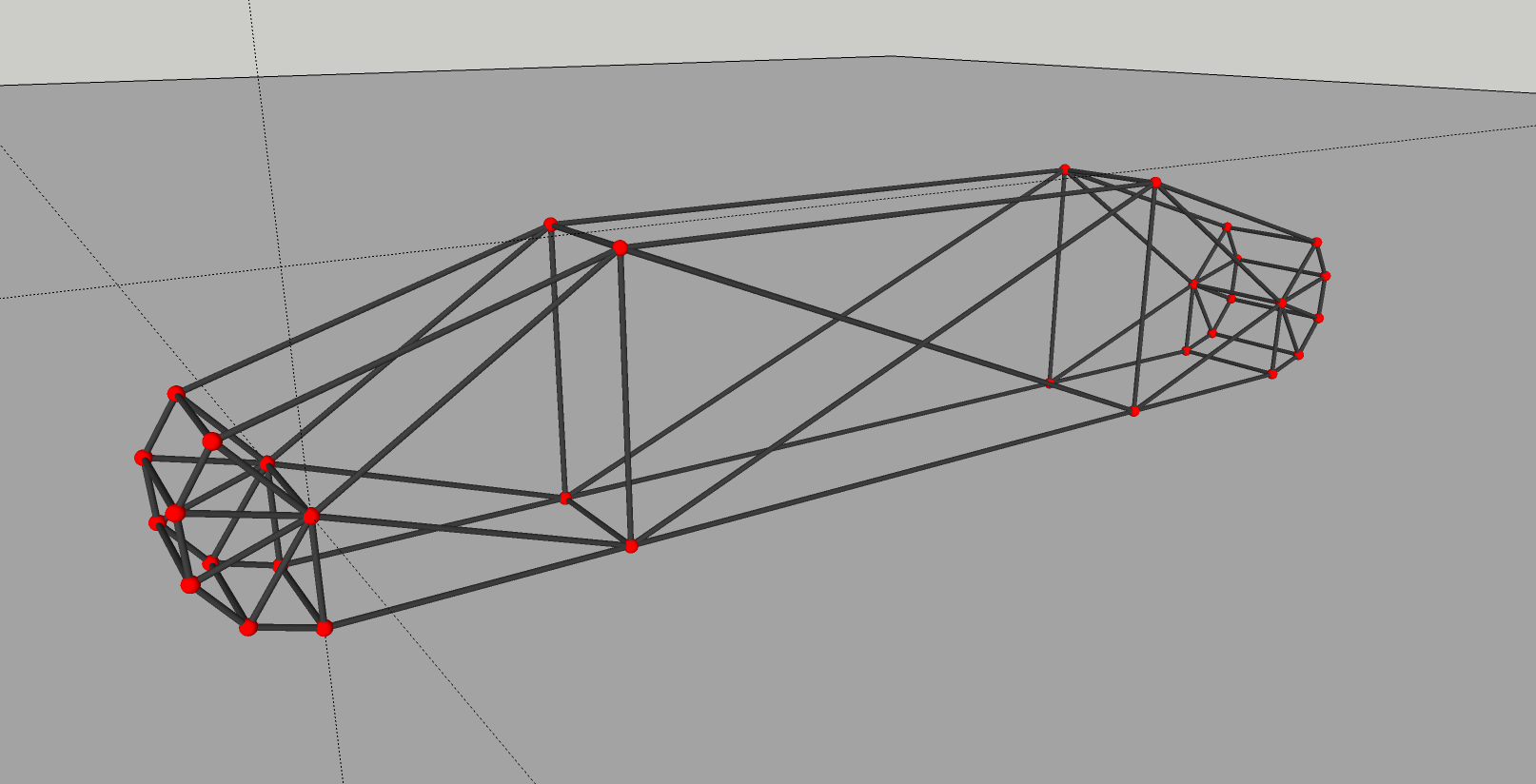
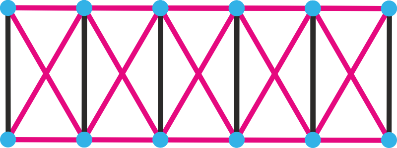
The shape of the frame always varies depending on the vehicle you make or how you want to make it, of course. The picture shows a very simple structure of a crawler crane/excavator frame. And by simple I mean I have left out a lot of beams to make it easier to see the structure, placement of nodes etc.
The ends of the frame as you can see, consist of a group of nodes (nodes 1-5), forming a rounded end. Depending on the number of nodes you use, and how well you place them, determines how well and smoothly the track chain will bend around the ends.
The example as you can see uses 10 nodes on each end, or 5 nodes when you see from the side, which makes a fairly smooth bending.
To help making a good half-circle shaped bending, you can temporarily place a wheel (not showed in the picture) on the "center node (node 6)" and follow the shape of the wheel. Then don't forget to enable viewing wheels in the editor (View> Wheels) and remove the wheel when you are done.
Note about the nodes: Don't forget to make the nodes of the bottom *of the crawler frame un-contactable with the ground with the "c" option for nodes.
Red dots = crawler frame nodes, Black tubes = crawler frame beams
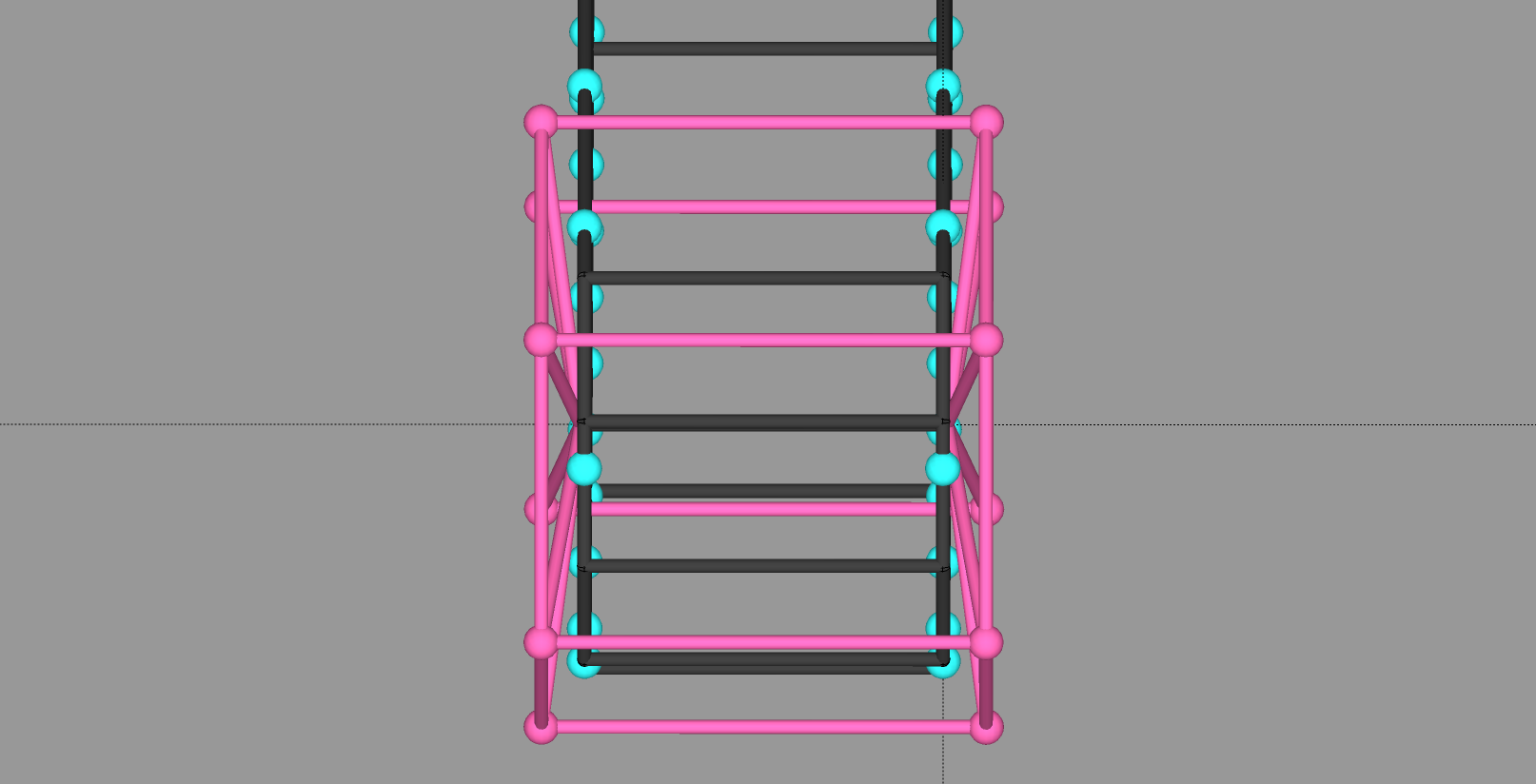
Step 2: Making the track links
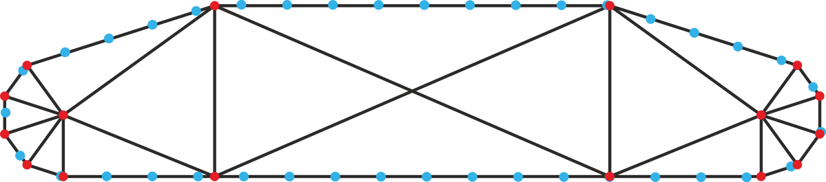
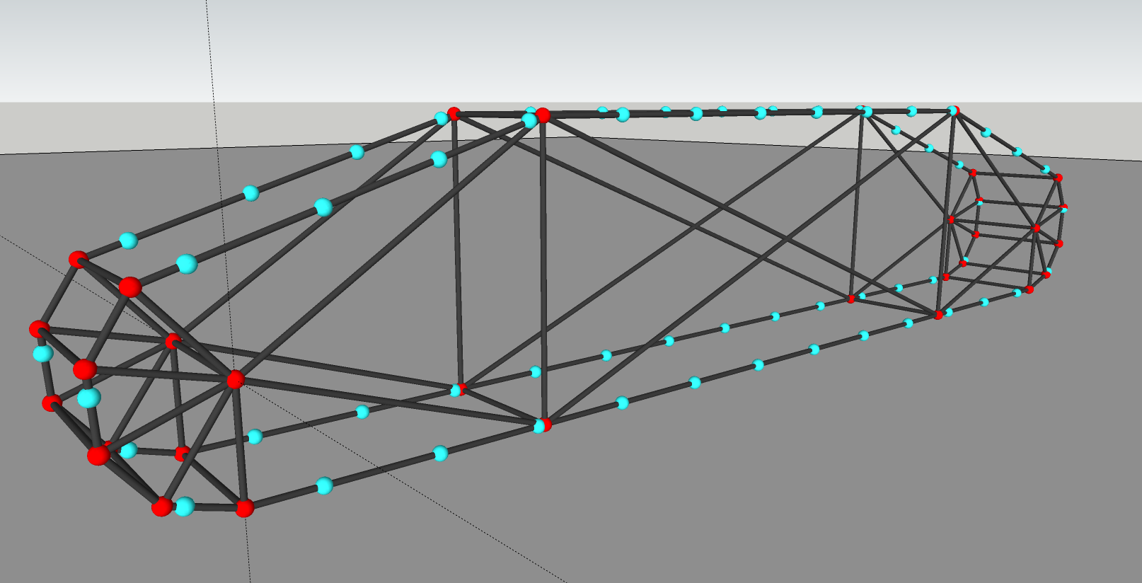
Placement: As the track link nodes will work as slidenodes going around the crawler frame, they should be placed pretty accurately on the beams forming the rail, and it is important that all track links are the same length. ± one centimeter or so doesn't matter, but avoid larger differences. There are some methods for this:
- Trigonometry, somewhat advanced math calculating.
- Making the N/B using a program like Blender, where you would be able to create
a long chain of links and then angle them to the correct position (I've never tried that in Blender, but it is possible right? ).
- Do like I did, using a physical ruler. Yes, I actually used a plastic ruler
on the computer monitor. Just begin by making one track link with a fitting length, measure the distance on the monitor between the nodes and continue placing the nodes with the ruler.
When the nodes are placed, it's time to define the slidenodes and rails in the truck file.
And don't forget to make all track nodes contactable, in order to be driven by the submesh in the sprockets
Blue dots = track nodes
Beams or shocks? In some cases the track links need to change length *in order to keep in place on the sliderail, and in most cases it's only about *a few millimeters. Therefore I would recommend using shocks for all the beams *in the track links except the ones going straight sideways:
Purple lines = shocks
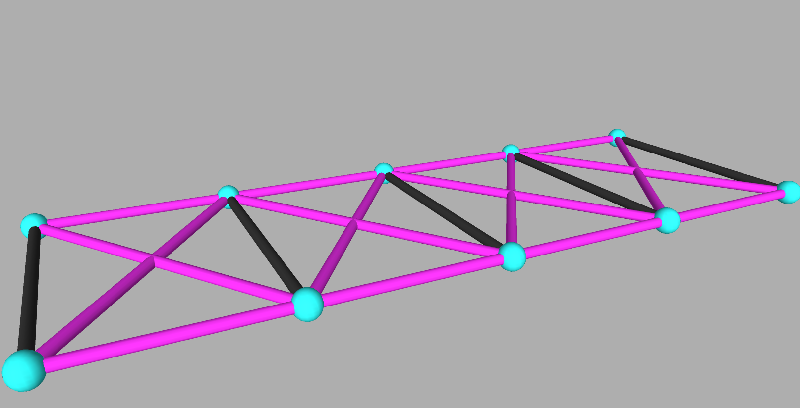
The shocks don't need to be able to extend or retract much at all, Maximum contraction and extension values like 0.05 for the shocks should work well.
Length and number of links? How long each track link shall be is up to you. The more links you make (the shorter they are), the more nodes does it take and therefore more FPS heavy, but it also drives more smooth. Snowcats and other similar all-terrain machines would be more realistic with a larger number of track links, while heavy machines like excavators and crawler cranes could use less as they are driving quite slow.
Step 3: Making the driving sprocket
Size: The sprocket should not be too big or too small. If it is too small, there is a chance the nodes will slide/jump over the submeshes in the sprocket. If it is too big it's not good either, how I shall explain this though, I don't know.
In the example below, the size of the sprocket compared to the "bending frame" thingy is fairly good.
Number of "sections": In my example below the sprocket is built up by 6 "sections". How many sections that are needed depends on size of the track and the length of the track links.
When you have built the basic structure of the sprocket, add the contactable submesh and use the "U" option for contact. Since the submesh is supposed to be invisible, simply skip the "texcoords" lines and add only "cab" lines.
"Light pink" dots and lines = sprocket nodes and beams
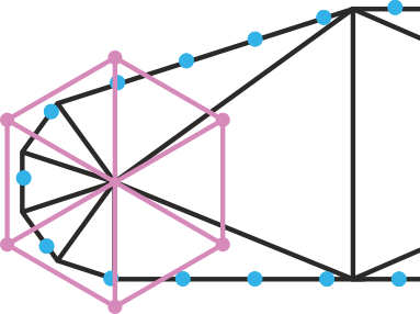
Also keep in mind that the sprocket always need to be wider than the track itself.
One or two sprockets?
Depending on the kind of vehicle, how much force is applied to the tracks, how many nodes you are willing to use etc, you may want to make either one or two driving sprockets per track. If you want two sprockets, it is very easy to drive the other sprocket with the first one (the one that is driven by the rotator, see further down for how to make the rotators).
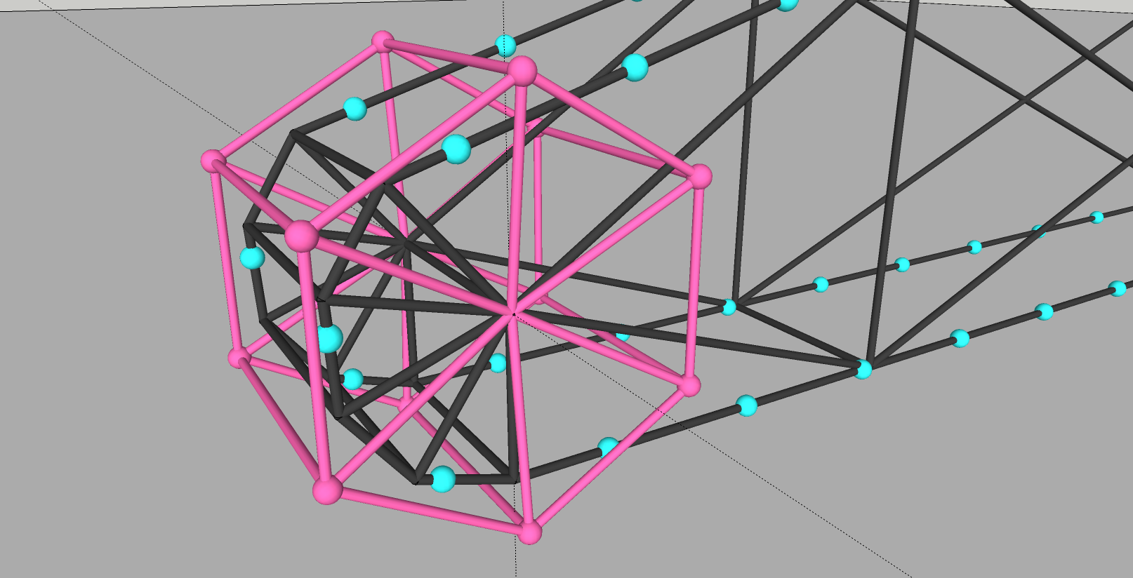
In the example with the 6-section sprocket, it can be done easily by connect three beams per side like the picture shows:
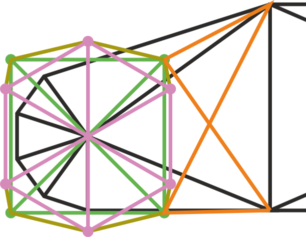
Step 4: Making the rotator for the driving sprocket
Now it's time to define rotator for the sprocket. The size of the rotator can without problems be about the same size *as the sprocket itself, But it's recommended that you don't make the rotators *too small, for this matter: ((TODO: fix link)) *[http://www.rigsofrods.com/threads/66248-Rotators-flexing-%28flexing-rotation-force-NOT-beams%29]
Note: Don't forget to make the nodes of the rotators sprockets *un-contactable with the ground with the "c" option for nodes.
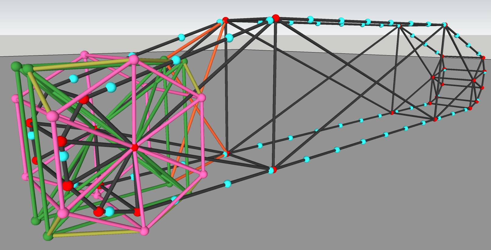
Green: Rotator, Olive green: beams connecting the rotator to the sprocket Orange: beams connecting the rotator to the crawler frame.
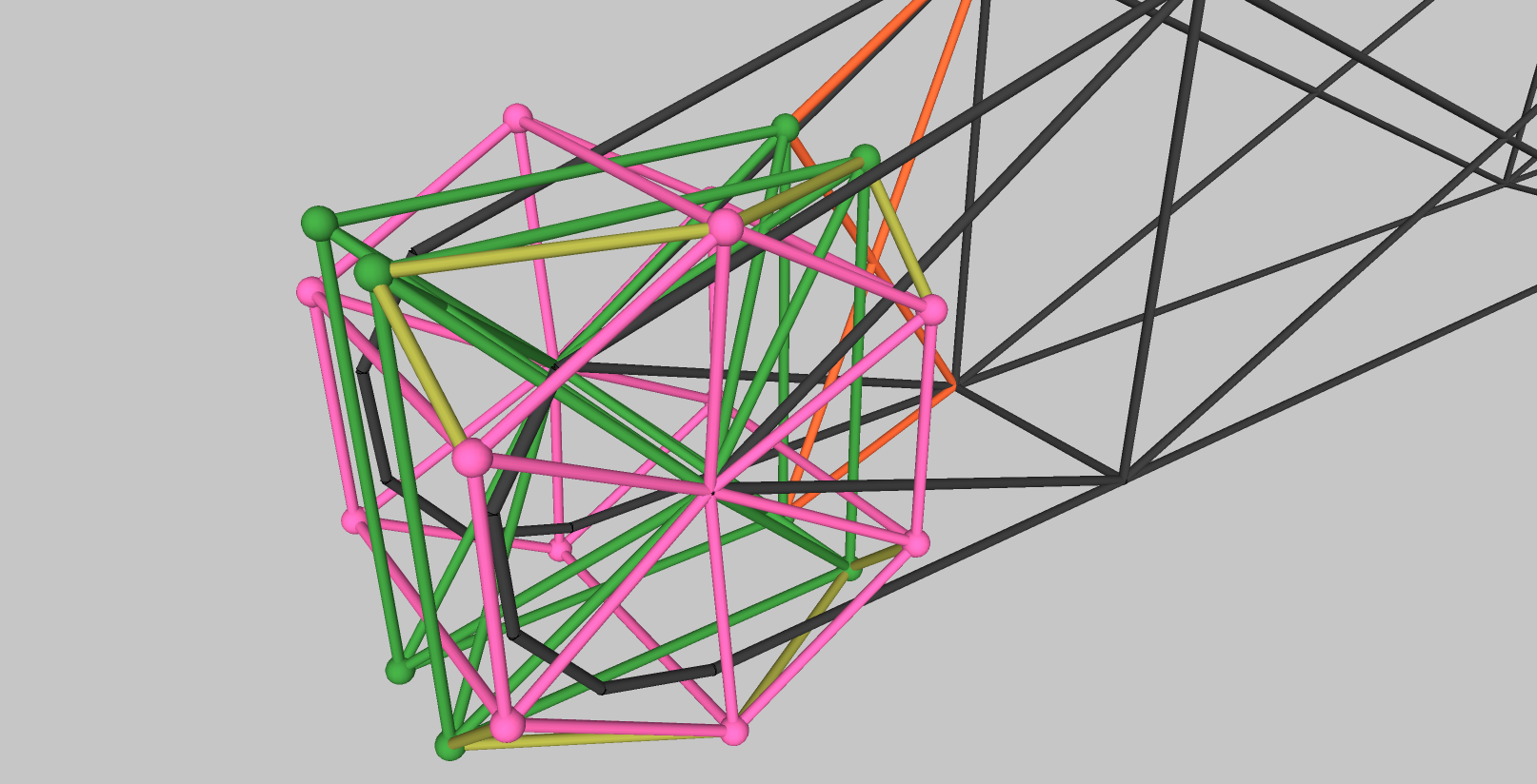
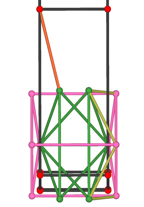
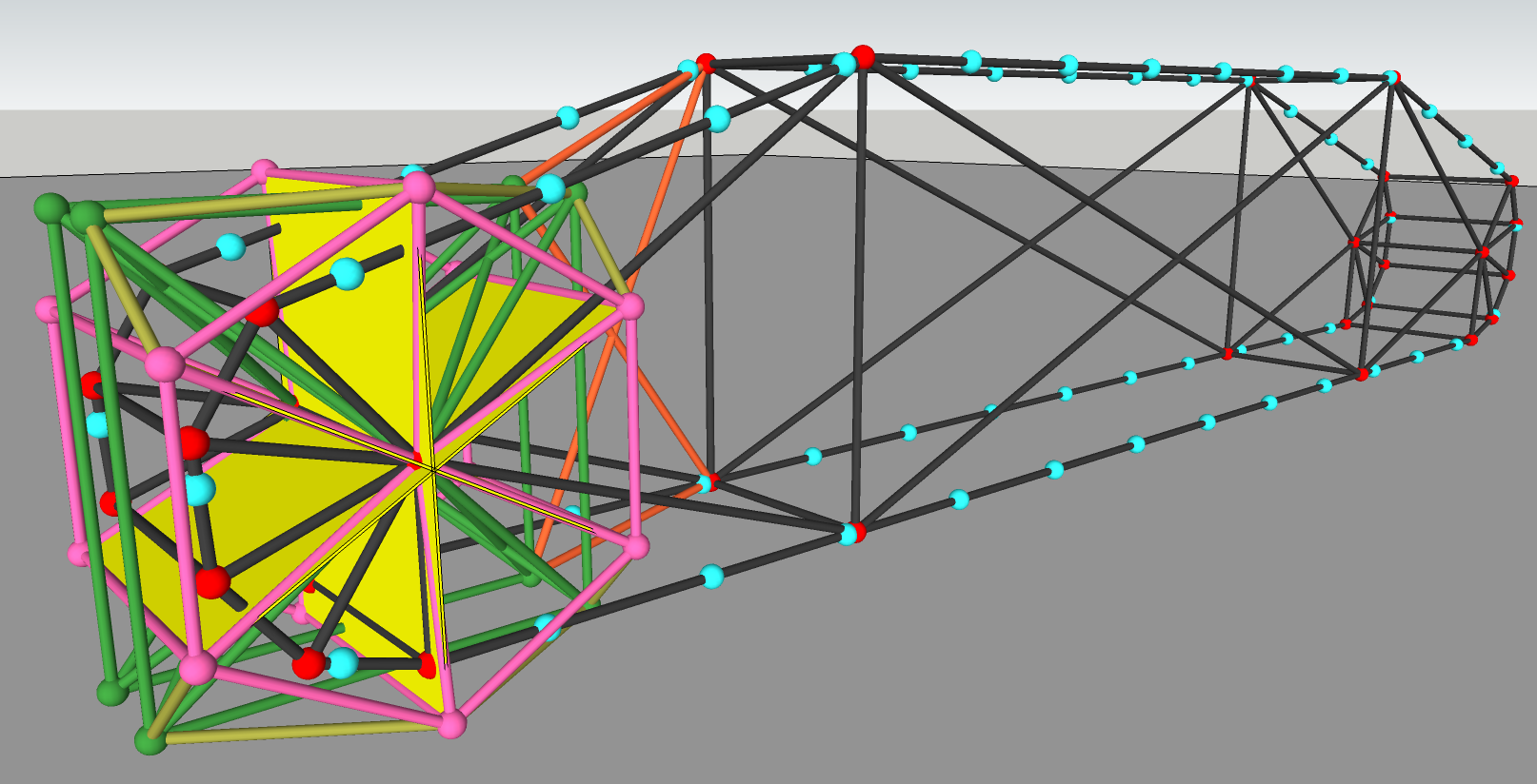
The finished result looks something like this (track link beams are left out). The yellow planes in the 2nd picture are the submesh (will be invisible ingame).
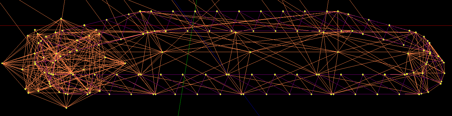
This is the right track of my crawler crane, viewed in Blender with plugins:
Hope it was helpful!
This tutorial was created by AIN_002 and added to the (retired) wiki by Steve Ror Fan.