Aircraft and aerodynamics
Wings
Wings in RoR are a little bit of magic. They introduce aerodynamic effects onto planes, boats, and trucks. Although propulsion engines (motors, props, screws) cannot be combined, wings can be added to any sort of vehicle to provide aerodynamic force.
Introduction
The wing section declares parts of the chassis as wings, and that they should bear aerodynamic forces. Each line of this section designs a '''wing segment''', that is a homogeneous part of a wing. You can (and you should!) make a plane's wing from several contiguous wing segments. Rudder and elevators are also made with one or more wing segments.
Each wing segment is bounded by 8 nodes, that defines the "bounding box" of the wing, specifically its span, chord and thickness. You must ensure that these nodes are properly interconnected by beams to ensure the structural integrity of the wing.
'''Notice that it is VERY IMPORTANT to declare contiguous wing segments''' (i.e. that shares nodes) IN SEQUENTIAL ORDER FROM RIGHT TO LEFT, and you should avoid cutting a wing in two at the fuselage, but make the whole wing continuous across the fuselage because it helps to compute whole-wing effects like induced drag and other things like wing lights.
A very important aerodynamic parameter is the wing airfoil. The airfoil is the tear-like shape of the wing, and its exact geometry is very important for the characteristics and performances of real-world wings. RoR uses precomputed performances curves from standard airfoils, interpolated from wing tunnel tests. These curves are stored in .afl files.
Airfoils
Standard airfoils provided in RoR are: * NACA64.1.412 - actual airfoil of the wing tip of the Hercules C-130 * NACA64.3.618 - similar airfoil to the wing root of the Hercules C-130 * NACA0009 - standard symmetrical airfoil, good for rudder and elevators * Clark-Y - used for propellers, but is also very popular for main wings
You can get more airfoil from the popular X-Plane flight simulator. RoR is compatible with X-Plane .afl, but you must convert their end-of-line style from MacOS to Windows using an advanced text editor, or RoR will crash.
Example Wing
Here's an example:
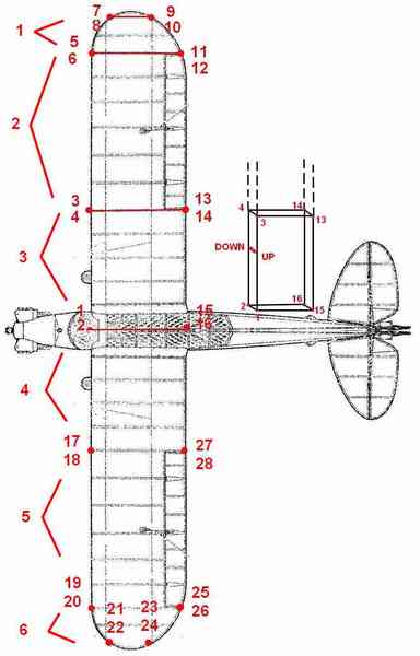
And the corresponding wings section :
wings
;right wing
;1
6,8,5,7,12,10,11,9, 0.509, 0.999, 0.555, 0.751, 0.752, 0.999, 0.752, 0.751, n, 1.0, 0, 0, NACA64.1.412.afl

;2
4,6,3,5,14,12,13,11, 0.509, 0.999, 0.555, 0.751, 0.752, 0.999, 0.752, 0.751, a, 0.75, -24, 24, NACA64.1.412.afl

;3
2,4,1,3,16,14,15,13, 0.509, 0.999, 0.555, 0.751, 0.752, 0.999, 0.752, 0.751, n, 1.0, 0, 0, NACA64.1.412.afl


;left wing
;4
18,2,17,1,28,16,27,15, 0.509, 0.999, 0.555, 0.751, 0.752, 0.999, 0.752, 0.751, n, 1.0, 0, 0, NACA64.1.412.afl

;5
20,18,19,17,26,28,25,27, 0.509, 0.999, 0.555, 0.751, 0.752, 0.999, 0.752, 0.751, b, 0.75, -24, 24, NACA64.1.412.afl

;6
22,20,21,19,24,26,23,25, 0.509, 0.999, 0.555, 0.751, 0.752, 0.999, 0.752, 0.751, n, 1.0, 0, 0, NACA64.1.412.afl
Air Brakes
(Version 0.35 or later)
An air brake is a moving panel used to slow down an airplane. It is positioned similarly to a "props", with noderef, nodex, nodey, nodea, offsetx, offsety, offsetz
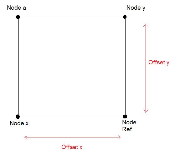
The airbrake needs 4 nodes (noderef, nodex, nodey, nodea) to position it.
pick 4 nodes that form a square or rectangle at the position you want your airbrake. This picture shows a basic airbrake setup, you can see the offsetx, and offsety in red move the airbrake back and forth along that direction. Offset Z will move it up and down vertically (in this case).
It takes time to position a airbrake just right. Make one adjustment at a time and see what the change did in game before you make another. The 4 nodes you choose will determine the direction your airbrake points. If the airbrake is backwards, swap the noderef, nodex, nodey, nodea around until it points the way you want.
Width and length control how long or wide the airbrake is. Simply adjust these numbers until the airbrake is the size you want.
Max angle is the maximum angle the airbrake will lift when fully engaged. Then comes two texture coordinates that texture the airbrake using your vehicles texture pic.
Air brakes can easily be added to a wing box, just set noderef, nodex, nodey and nodea as the four upper nodes of a wing box.
Example:
airbrakes
; noderef, nodex, nodey, nodea, offsetx, offsety, offsetz, width, length, max angle, texcord x1, texcoord y1, texcoord x2, texcoord y2
95, 105, 113, 125, 0.2, 0.0, 0.0, 2.0, 3.0, 60.0, 0.044, 0.205, 0.124, 0.146
Propeller engines
To add a propeller engine to your creation, first you need to make the node and beam part of the engine (its the same for either type of engine, turboprop or pistonprop).
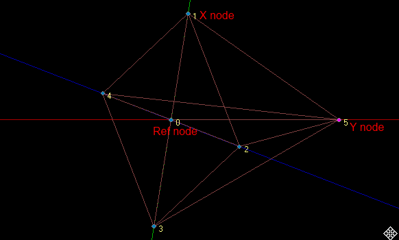
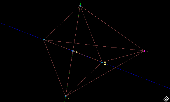
You start off by making a diamond shape with one node in the middle, like so:
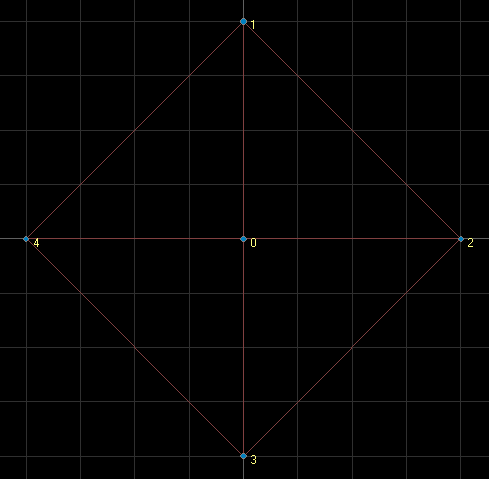
Make sure that all the nodes are evenly placed so that when they're spinning at high RPM's they won't get out of balance. (You can get them spot on in the editorizer if you use the "snap nodes to grid" option). Now you need to add another node in the center of that diamond but this one needs to be a bit behind the first middle node. Like so:
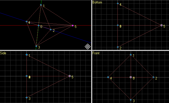
now just connect all the nodes together with beams but make sure you only connect the diamonds four outer edge nodes (in this case nodes 1,2,3 and 4) to each other to make an out line and then to the 2 middle nodes. Its important that this is done so that they can rotate smoothly. The nodes that you would use to attach the engine node/beam assembly to the rest of the planes chassis would be the two middle nodes (in this case nodes 0 and 5).
Now that you have the node and beam part of the engine done you can move on to the truck file code part of the engine.
== Props section requirements ==
First we will take care of the "props" section.
'''Note: it is important that you have the "props" section ''BEFORE'' the turboprops or pistonprops section.'''
The first thing that you want to add to the props section is the "spinprop.mesh" this is what makes the turboprops/pistonprops work. When placing this mesh its important how the nodes that you place it on are oriented, for this test model that I'm making it would have ref node: 0, X node: 1, Y node: 5 this way when the engine is spinning the propeller mesh (ie pale.mesh) will be oriented right. for example if I switch X and Y around so X was 5 and Y was 1 the propellers would appear to spin at a 90 degree angle compared to the way the node/beam engine was really spinning. Also you need one "spinprop.mesh" for each engine you have.
Example props section for "spinprop.mesh":
props
;ref,x,y,offsetx,offsety,offsetz,rotx,roty,rotz,mesh
0,1,5, 0.0, 0.0, 0.0, 0, 0, 0, spinprop.mesh
The next thing we need to add to the props section is the propellers mesh. Its the same as for the "spinprop.mesh" you just need one for every visible propeller you want. By looking at the picture and the example props section below it should be fairly easy to figure out.
Example props section with propellers mesh's:
props
;ref,x,y,offsetx,offsety,offsetz,rotx,roty,rotz,mesh
;First propellers mesh
0,5,1, 0.0, 0.0, 0.0, 180, 0, 90, pale.mesh
;Second propellers mesh
0,5,2, 0.0, 0.0, 0.0, 180, 0, 90, pale.mesh
;Third propellers mesh
0,5,3, 0.0, 0.0, 0.0, 180, 0, 90, pale.mesh
;Fourth propellers mesh
0,5,4, 0.0, 0.0, 0.0, 180, 0, 90, pale.mesh
Turboprops section
Now that you have everything done in the props section we can move on to the turboprops section.
The turboprops section has 8 parameters they are: * 1. Reference node number (center of the prop) * 2. Prop axis node number (back of the prop) * 3. Blade 1 tip node number * 4. Blade 2 tip node number * 5. Blade 3 tip node number * 6. Blade 4 tip node number * 7. Power of the turbine (in kW) * 8. Airfoil of the blades
Explanation of the parameters for the example engine built for this tutorial: * The first parameter is the reference node which in this case would be node number 0. * The second parameter is the back node of the prop which in this case is node number 5. * The third parameter is the first blades tip node number, in this case node 1. * The fourth parameter is the second blades tip node number, in this case node 2. * The fifth parameter is the third blades tip node number, in this case node 3. * The sixth parameter is the fourth blades tip node number, in this case node 4. * The seventh parameter is the amount of power of the engine, in this case 3000.0. * The eighth parameter is the airfoil that the props will use, in this case "Clark-Y.alf".
Example turboprops section:
turboprops
;ref, back, p1, p2, p3, p4, power, propfoil
0,5,1,2,3,4, 3000.0, Clark-Y.afl
Pistonprops section
The pistonprops section is pretty much the same as the turboprops section only with 2 more parameters and different sounds in-game.
- The first parameter is the reference node which in this case would be node number 0.
- The second parameter is the back node of the prop which in this case is node number 5.
- The third parameter is the first blades tip node number, in this case node 1.
- The fourth parameter is the second blades tip node number, in this case node 2.
- The fifth parameter is the third blades tip node number, in this case node 3.
- The sixth parameter is the fourth blades tip node number, in this case node 4.
- The seventh parameter is the couple node, which in the example is not used so it is set to -1. Also from my searching the couple node parameter was never documented so I don't know what its purpose is.
- The eighth parameter is the amount of power of the engine, in this case 3000.0.
- The ninth parameter is the pitch of the prop, in this case it is set to -10
- The tenth parameter is the airfoil that the props will use, in this case "Clark-Y.alf".
pistonprops
;ref, back, p1, p2, p3, p4, couplenode, power, pitch, propfoil
0,5,1,2,3,4, -1, 3000.0, -10, Clark-Y.afl
Set_beam_defaults
Its quite possible that you will have to use set_beam_defaults to make it so that your engine doesn't explode once you have it spinning. First I would try with out using set_beam_defaults and if the engines explode when spinning I would add set_beam_defaults to the engines beams and raise the deform and break values until you can run the engine at full throttle with out it breaking. The settings that this example uses may be a bit extreme but you get the idea.
set_beam_defaults to start out with when raising the deform and break values:
;        spring, damping, deform, break,
set_beam_defaults -1, -1, 400000, 1000000,
set_beam_defaults that the example engine uses:
;         spring, damping, deform, break,
set_beam_defaults -1, -1, 2000000, 3000000,
Fusedrag
A fuse drag can be used for a couple of things.
It can be used to make a vehicle more aerodynamic to make the top speed improve.
The fusedrag section can help improve modelling of the aerodynamic drag of a plane.
It can model the fuselage of a plane like a big wing section, with an airfoil.
An example of a symmetrical airfoil is something like NACA0009.afl
I'm going to show you improvements a fusedrag can do to a vehicles top speed.
An example I'm going to use the Dodge Police.
The max speed without wheel spin was about 41 mph.
Now let's add a fusedrag and see what happens.
To add a fuse drag just find two nodes.
Here is what needs to be defined:
- Number of the front-most node of the fuselage: First Node
- Number of the rear-most node of the fuselage: Second Node
- Approximate width of the fuselage: ie: 4.0 (You can use and width you want.)
- Airfoil name: (Default NACA0009.afl)
Here's an example of what i added in the .truck file.
fusedrag 10, 11, 4.0, NACA0009.afl
I got an result, the speed improved by 31mph so if you want more speed add a fusedrag.