Truck file format
"Truck" is a text-based file format which defines all physically simulated objects in the game, be it vehicles of any kind, machinery, loads or any other things. The name is historical - Rigs of Rods was originally a heavy truck simulator, other kinds of vehicles came later.
Recognized filename extensions for this format are: .truck, .car, .boat, .airplane, .train, .machine, .trailer, .load, .fixed. Note the extension is only informative, the actual type of object is determined by file contents.
The truckfile is divided into sections, each with defined purpose. Except the title, every section starts with a keyword. Order of sections matters (for example: cinecams requires beams).
Comment lines can be inserted by putting ; or // at the beginning of the line.
Building Philosophy
See Vehicle Concepts to understand the building philosophy.
Is It a Truck, Plane, Train or Boat?
Before we start, let's ask an important question: Is it a truck, plane, train, or boat? Or what makes a truck a truck and a plane a plane and a train a train, or a boat a boat? Simple:
- A truck is a description file containing an engine section
- A plane is a description file containing a turboprops, turbojets, or pistonprops section
- A boat is a description file containing a screwprops section
- A train is a vehicle that drives on a rail (see Building rail vehicles)
Also, notice that:
- You should not combine more than one propulsion (eg have both an engine and a turboprops section in the same file)
- If you have no propulsion, then you are making a load, and the file extension should be
.load - You can have a wings section on a truck or a boat (e.g. to add aerodynamic spoilers for stability).
- You should have a fusedrag section on a plane to have a better aerodynamic modeling.
- A boat needs to have a hull which is defined in the submesh section.
Light Cars
Here a few recommendations for those who want to build a light car: RoR is optimized for heavy trucks, so you have to use some extra sections that help you create a realistic car:
- Use engoptions to reduce the engine inertia and set the engine type to c
- Use brakes to reduce braking force
- Use and abuse set_beam_defaults to soften the car body, or it will be too strong and springy, i.e. almost indestructible.
- Experiment with the engine section to use higher RPM and correct gear ratios.
- Lighten the wheels as much as possible. This is not very easy as they become unstable. Reducing the spring and damping of the wheels helps a lot. Suggested values for 100kg wheels: spring
150000and damping1000. - Use the dashboard-small.mesh prop as a dashboard. (unless you have a custom dashboard you want to use.)
Documentation style guide
Every keyword (directive, inline-section or section) which has parameters should have them listed in this manner:
- Required parameter: Data type; default =
VALUE; Explanatory text. - Example required parameter: Real number; default =
-1.0; Parameters are written as shown, followed by a colon. The data type should be easy to understand for a human, not technically accurate. - Another required parameter: Positive decimal; The "default" text can be omitted if the parameter has no default. The "data type" field should always be followed by semicolon.
- Optional parameter (optional): Data type; default =
VALUE; Optional parameters have "(optional)" text after them. Alternatively, the parameter list may be split into "Required parameters" list, followed by "Optional parameters" list, see 'flares'. - Required nullable parameter (nullable): Data type; Empty value =
-1; Parameters which must be entered but can contain "empty value" are described (nullable) and have "Empty value" section. - New parameter (optional): [ Version 0.4+ ] Data type; Parameters with version requirements have a [ Version ] box.
- Options (optional): String, default = none Options are enumerated as sub-list.
a: What this option does.b: Another optioncorC: Case insensitive option.
Required Sections
The game will not run without these sections. Every one of these sections must be present for a vehicle to work in the game!
Title
This is the only section not introduced by a keyword. It is the name of the truck, and it absolutely positively must be the first line of the file.
My nice truck
Globals
This section defines some global parameters. Those parameters are:
- dry mass - Real number; The weight RoR will try to give the truck (affected by minimum node weight, see below). Weight is measured in kilograms. (For you people in non-metric countries, a kilogram is 2.2 pounds.)
- Load mass - Real number; Total mass of all nodes marked with the option "l".
- Material name - String; The name of the material that will be used to texture the truck's submesh. This material must be defined in a separate material file.
globals
;dry mass, cargo mass, material
10000.0,  1000.0,     tracks/semi
Nodes
This section begins the structural definition of the vehicle. Each line defines a node.
- Node number: Positive decimal number; The first parameter is the node number. These numbers must be consecutive. Important: Do NOT use node 0 for any moving stuff like propellers, commands etc. It's the reference for some calculations in RoR and should be part of the rigid frame of your truck.
- X position (in meters): Real number; Node's X coordinate.
- Y position (in meters): Real number; Node's Y coordinate.
- Z position (in meters): Real number; Node's Z coordinate.
- Options (optional): String; default = none; Node options. You can combine multiple flags.
- n: This node can be grabbed with the mouse. (Standard node)
- m [ Version 0.39.07+ ]: This node can't be grabbed with the mouse. (Useful for switching levers with the mouse.)
- f: This node will not produce sparks. (Useful for support feet or hand made wheels.)
- x: This node is the exhaust point. (requires a "y" node) (see the exhausts section)
- y: The exhaust reference point. This node should be placed opposite of the direction that you want the exhaust to come from.
- c: This node will not detect contact with ground. (Can be used for optimization on inner chassis parts, for instance.)
- h: This node is a hook point. (Like the hook on a crane, or a winch, or whatever.) RoR will create a beam between this Node and Node#0. If this is Node#0, it will link it to Node#1 (even if it isn't defined yet).
- e: This node is a terrain editing point (Like in the terrain editor truck. Not used as of version 0.4.0+)
- b: This node is assigned an extra buoyancy force (Experimental!)
- p [ Version 0.36.3+ ]: Disables particle effects for this node (Like dust.)
- L [ Version 0.36.3+ ]: Enables node settings logging into the ror.log for this node
- l: This node bears a part of the cargo load
- Load mass (in Kilograms) (optional, needs l flag): Real number; Overrides the load mass for this node. Only valid if used with l option. Please note that the load-nodes where you specify the mass explicitly are not calculated with the global load mass. So if you specify a custom mass on any load, you will also increase the mass on all other nodes if you do not decrease the global mass.
NOTE: You can put a comment at the end of a node-line.
nodes
;id,    x,    y,    z,     options
;main chassis
0, 0.00, 0.75, 0.66
1, 0.00, 0.75, 1.84
2, 0.63, 0.75, 0.66
3, 0.63, 0.36, 0.66, l
4, 0.63, 0.75, 1.84
5, 0.63, 0.36, 1.84, n
6, 1.48, 0.75, 0.66, l
7, 1.48, 0.00, 0.66
8, 1.48, 0.75, 1.84, c
9, 1.48, 0.00, 1.84, x
10, 2.33, 0.75, 0.66, y
11, 2.33, 0.00, 0.66
This section supports multiple options as argument.
If you want a f and b node together you could write something like this:
nodes
11, 2.33, 0.00, 0.66, fb
This setting will set the node mass to 2000 kilograms:
nodes
14, 1.36, 0.00, 1.97, l 2000
This setting will set the node as non-contactable and set the mass to 2000 kilograms:
nodes
14, 1.36, 0.00, 1.97, cl 2000
You can debug your truck's node masses by enabling Debug actor mass in settings:
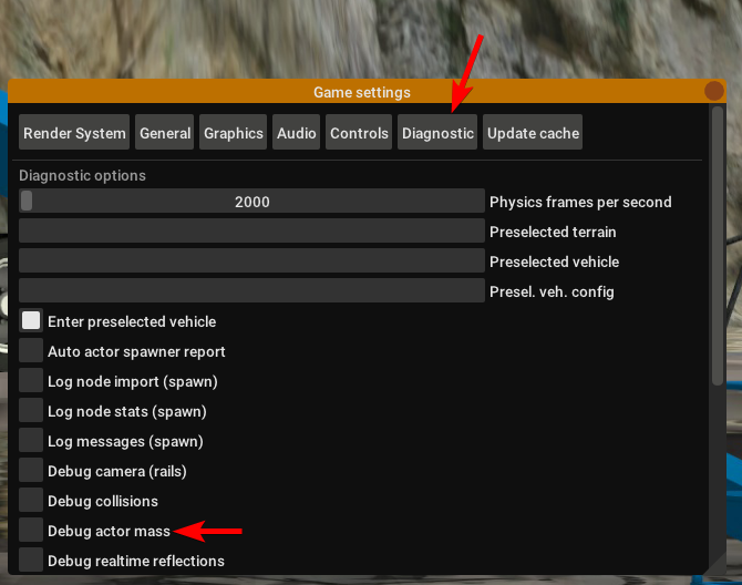
Look into your RoR.log after spawning and you could see something like this:
Node 0 : 3662 kg
Node 1 : 1730 kg
...
Node 13 : 1180 kg (normal load node: 6000 kg / 6 nodes)
Node 14 : 1180 kg (normal load node: 6000 kg / 6 nodes)
...
Node 136 : 5026 kg (overridden by node mass)
Node 141 mass (20kg) too light. Resetting to minimass (50kg).
...
TOTAL VEHICLE MASS: 32399 kg
You can set any option property, loadweight, friction, volume, and surface-coefficients as default with set_node_defaults.
Nodes2
Nodes2 use the same syntax as nodes, except the first argument can be any string instead of a number. After using a name for a node in the nodes2 section, you can use it for any node parsing throughout the rest of the file. valid characters for the string: a-z,A-Z,0-9, _
For example:
nodes2
; name,    x,    y,    z,     options
; main chassis
0, 0.00, 0.75, 0.66
1, 0.00, 0.75, 1.84
special_node, 0.63, 0.75, 0.66
3, 0.63, 0.36, 0.66,l
4, 0.63, 0.75, 1.84
another_one, 0.63, 0.36, 1.84
hook_node, 1.48, 0.75, 0.66,lh 50
We advise to use the following scheme for naming the nodes:
function_section_name
So for example a rear hook node could look like this:
hook_rear_hook1
There is also a fallback in place which will resolve named nodes to normal node numbers. For example if you convert an existing truck to named nodes (nodes2) and don't want to replace all occurrences, just leave the numbers there, it will take them up as classic node numbers.
Things to keep in mind:
- Transition from
nodestonodes2is easy: just replacenodeswithnodes2, the numbers will act as the name strings - Transition from
nodes2tonodesis impossible, since nodes rely on the linear numbering of nodes - Only use node names without any special characters or spaces (only a-z, A-Z, 0-9, _, -)
- You don't need to convert all nodes to nodes2 with names, if a nodes2 named node is not found, it will fallback to using the number as classic node.
Beams
This section defines all the beams connecting nodes. Each line describes a beam.
- node_A: Node ID; Connected node
- node_B: Node ID; Connected node
- options (optional): String; default = empty
- v: Dummy option, does nothing. Beams are visible by default.
- i : This beam is invisible.
- r : This beam is a rope (no resistance to compression, but will deform/break when expanded)
- s : This beam is a support beam (no resistance to expansion, but will deform/break when compressed). Support beams have 1/10th of the damping of the last set_beam_defaults setting
- extension_break_limit (optional): Positive real number; default = 4 * original length; Only valid with option "s"
TIP: Support beams are very useful for limiting movement of body panels like trunks, hoods, and doors from going inside the car while still allowing rotation without costly and complicated collisions. Default expansion break length is . User set break length factor is optional. Valid factors are > 0.0. .
beams
;node1, node2, options
0,     1
2,     4
3,     5,        i
6,     8,        i
7,     9
10,    12,       i
11,    13,       i
; support beam, default extension break limit
11,    23,       s
; visible support beam, user set extension break limit original spawn length * 12.5
11,    24,       s 12.5
This section supports multiple options as argument. If you want a 'i' and 'r' node together you could write something like this:
;invisible rope
11,    13,       ir
; invisible support beam, default extension break limit
11,    25,       is
; invisible support beam, user set extension break limit original spawn length * 25
11,    26,       si 25.0
Cameras
This section is important. It helps to position the truck in space, by defining a local direction reference. This is used to measure the pitch and the roll of the truck. It is also very important to orient the truck's cameras.
The three parameters are node numbers. The first is the reference node and may be anywhere. The second must be behind the first (if you look at the front of the truck, it is hidden behind the first). The third must be at the left of the first (if you look to the right of the truck, it is hidden by the first).
Correct relative placement of these nodes is important, or it may break the inside camera view.
cameras
;center, back, left
0, 2, 1
Cinecam
This defines the position of the in-truck camera. It is a special node suspended from eight chassis nodes.
Required parameters:
- X,Y,Z position (in meters): Real numbers; Coordinates of the camera point.
- 8 node bindings: Node ID; Nodes to which the camera point is bound.
Optional parameters:
- beam spring: Real number; Default=8000
- beam damping: Real number; Default=800
- node weight (Kg): Real number; [ Version 2020.01+ ] Weight of the camera point. Default=20Kg
Example:
cinecam
;  x,   y,   z, <---------8 bindings--------->, Opt: spring, damping, node-weight
0.66, 2.0, 1.8, 75, 76, 77, 78, 73, 74, 53, 54,      8000.0,   800.0,        20.0
Note: If you have multiple cinecams, you also need to have multiple cameras. You can simply duplicate the line per cinecam. Example:
cameras
;center, back, left
0, 2, 1
0, 2, 1
0, 2, 1

cinecam
;  x,   y,   z, <---------8 bindings--------->, Opt: spring, damping, node-weight
0.66, 2.0, 1.8, 75, 76, 77, 78, 73, 74, 53, 54,      8000.0,   800.0,        20.0
0.56, 1.0, 1.4, 74, 75, 76, 77, 72, 73, 52, 53,      8000.0,   800.0,        20.0
0.36, 2.5, 1.9, 70, 75, 73, 76, 74, 79, 53, 50,      8000.0,   800.0,        20.0
End
This section will stop the parser. Everything after it will be ignored.
Since [ Version 0.4.5.0 ], it's optional. In previous versions it's STRICTLY REQUIRED - without it, the vehicle will crash the game.
end
Organizational Sections
These sections are not required, but will make it easier to locate your file or work with. Do not use carets in your syntax, they are used to mark sections!
GUID
You should use the guid feature to allow RoR to recognize your truck uniquely.
This section is required for skins.
;guid <GUID>
guid 6daaee29-e462-4d99-96d2-4577294f7b10
You can generate some GUIDs here.
Default_skin
Overrides the pre-selected skin of the truck. The specified skin will be displayed at the top of the skin selector instead of the dummy "Default skin" entry.
If no other skins are available, the skin will be applied automatically.
;default_skin <skin_name_with_underscores_for_spaces>
default_skin My_Awesome_Skin
Fileformatversion
This tells RoR what version of RoR your truck is built for. Most trucks built today should use fileformatversion 3
- Version 1 = Pre-RoR 0.32
- Version 2 = RoR 0.32 - 0.35
- Version 3 = Post-RoR 0.36
- Leaving out this tag will result in version 1.
fileformatversion 3
Author
author <Type> <AuthorID> <AuthorName> <Email>
-
Type = Tells what the author referenced in the next section did. Recommended types to put: chassis, texture, support, etc.
-
AuthorID = ID of the author's RoR Forum account. To get your ID, view your forum profile and check the number shown in the URL. For example:
https://forum.rigsofrods.org/members/curiousmike.5831/
5831 would be the ID.
-
AuthorName = The author's username.
-
Email = The author's e-mail. (optional)
Each author requires a separate line.
author chassis 4    heinz_peter               heinz@mail.com
author texture 123  forname_surname_othername someuser@mail.com
author support 5487 otheruser                 otheruser@mail.com
Please note: Do not use spaces in the type, authorname, or email. Instead, use an underscore ( _ ). In the game, the underscore will be replaced with a space.
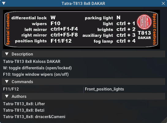
Description
description
Lorem ipsum dolor sit amet, consectetur adipisicing
elit, sed do eiusmod tempor incididunt ut labore et
dolore magna aliqua.
end_description
Pretty self-explanatory. Only the first 3 lines will get displayed in the Truck HUD. Do not put keywords in the description; they will mess up the truck file.
Fileinfo
General info about the vehicle.
-
Unique ID (nullable): String; default = -1; Empty value = -1; This field specifies the unique file ID (you get one by uploading it to the repository).
-
Category ID (optional) (nullable): Decimal number; default = -1; Empty value = -1; This is the category number from the repository. It is recommended that you give your truck a category.
-
File version (optional): Decimal number; default = 0; Version of the vehicle, read by users and the repository. For backwards compatibility, this field also accepts real number (a warning is reported).
; syntax:
;fileinfo <uniqueid>, <categoryid>, <fileversion>
; example:
fileinfo      000UID,          107,             2
Available category IDs
;;; vehicles
108, Other Land Vehicles

146, Street Cars
147, Light Racing Cars
148, Offroad Cars
149, Fantasy Cars
150, Bikes
155, Crawlers

152, Towercranes
153, Mobile Cranes
154, Other cranes

107, Buses
151, Tractors
156, Forklifts
159, Fantasy Trucks
160, Transport Trucks
161, Racing Trucks
162, Offroad Trucks

110, Boats

113, Helicopters
114, Aircraft

117, Trailers
118, Other Loads

;;; terrains
129, Addon Terrains

859, Container

875, Submarine

;note: these categories are NOT in the repository:
5000, Official Terrains
5001, Night Terrains

;do not use category numbers above 9000!
9990, Unsorted
9991, All
9992, Fresh
9993, Hidden
Help
The help section gives the name of the material used for the help image in the commands panel (CTRL+T). This material must be defined elsewhere in a material file.
help
tracks/semihelp
This is optional. (But it looks cool, so use it!)
Comments
Comments are ignored by RoR. They are useful for telling users what things do in the truck file. Comments can be put anywhere by putting a semicolon ( ; ) as the first character of the line to be commented.
You can also comment out several lines of text using this format:
comment
One morning, as Gregor Samsa was waking up from anxious dreams,
he discovered that in bed he had been changed into a monstrous vermin.
He lay on his armour-hard back and saw, as he lifted his head up
a little, his brown, arched abdomen divided up into rigid bow-like
sections. From this height the blanket, just about ready to slide off
completely, could hardly stay in place. His numerous legs, pitifully
thin in comparison to the rest of his circumference, flickered helplessly
before his eyes.
end_comment
hideInChooser
Excludes the vehicle/load from being shown in the vehicle menu on top of the screen. Place the single keyword somewhere in the vehicle/load file.
hideInChooser
Vehicle-specific
The following sections define important vehicle parts, like wheels, shock absorbers, and the like.
Engine
The engine section contains the engine parameters. Parameters are:
- Shift down RPM: Real number The engine speed at which the automatic transmission will shift down (gear 2 and up) or the clutch engages (driving off).
- Shift up RPM: Real number The engine speed at which the automatic transmission will shift up. Actual redline is this value x1.25.
- Torque: Real number Engine torque in newton-meters (N/m). The higher the value, the faster a truck will accelerate. RoR uses a flat torque model, usually correct for large intercooled turbo diesels.
- Global gear Ratio: Real number A global gear conversion ratio. (Final gear reduction ratio)
- Rear gear ratio: Real number Gear ratio of reverse. For every turn of the wheel the engine will have to turn this many times (not counting the differential ratio).
- Neutral gear ratio: Real number Gear ratio of neutral gear. 1.0 is a good one as it helps to distinguish between reverse and forward gears
- First gear ratio: Real number Gear ratio of 1st gear.
- Second/etc gear ratio: Real number Gear ratio of all further gears. Note there must be between 1 and 21 forward gears. The final gear must be followed by a -1 value (parser will emit a warning if the terminator is missing).
engine
;min rpm, max rpm, torque, differential, reverse, neutral,   1st,  2nd,  3rd,  4th,  5th,  6th...
  1000.0,  1500.0, 8000.0,         2.00,   10.85,   10.00, 13.86, 9.52, 6.56, 5.48, 4.58, 3.83, 3.02, 2.53, 2.08, 1.74, 1.43, 1.20, 1.00, -1.0
One good source of practical gear ratios is Eaton Fuller. To see the ratios, click the name of the transmission and find "Product Specifications Guide". It's wise to make sure you can get into final gear. If your vehicle decelerates in a gear you may not have enough power, or the gear ratio may be too high.
Engoption
Engoption sets optional parameters to the engine. It is mainly used for car engines. Parameters are:
- Engine inertia: Real number, default = 10.0. The default game value is correct for a large diesel engine. For smaller engines you probably want smaller values. 1.0 or 0.5 would be appropriate for small atmospheric engines, for instance.
- Engine type: One Character String, default = t. Valid types are t for truck engine and c for car engine. This parameter changes engine sound and other engine characteristics.
- Clutch Force (optional): [ Version 0.36.2+ ] Real number, default = 10000 for trucks, 5000 for cars.
- Shift Time: (optional): [ Version 0.36.2+ ] Positive real number, default = 0.2 seconds. Time (in seconds) that it takes to shift. Requires a defined clutch force parameter to work.
- Clutch Time (optional): [ Version 0.36.2+ ] Positive real number, default = 0.5 seconds. Time (in seconds) the clutch takes to apply. Requires a defined clutch force parameter to work.
- Post Shift Time (optional): [ Version 0.36.2+ ] Positive real number, default = 0.2 seconds. Time (in seconds) until full torque is transferred. Requires a defined clutch force parameter to work.
- Stall RPM (optional): [ Version 0.4.0.7+ ] Real number, default = 300. RPM where the engine will stall.
- Idle RPM (optional): [ Version 0.4.0.7+ ] Real number, default = 800. Idle RPM the engine should attempt to maintain.
- Max Idle Mixture (optional): [ Version 0.4.0.7+ ] Real number, default = 0.1. Defines the maximum amount of throttle the truck will use to maintain the idle RPM.
- Min Idle Mixture (optional): [ Version 0.4.0.7+ ] Real number, default = 0.0. Defines the minimum amount of throttle the truck will use to maintain the idle RPM.
- Braking torque (optional): [ Version 2020.01+ ] Real number, default = engine_torque / 5. Defines the amount of engine braking when you let go of the throttle.
engoption
;inertia, type, clutchforce, shifttime, clutchtime, postshifttime, stallRPM, idleRPM, maxIdleMixture, minIdleMixture
     0.5,    c,      5000.0,      0.75,        0.9,          0.75,     500,      700,           0.25,           0.06
;sample shift timings for a mid size truck
PROTIP: Use the "Engine inertia" value to make the engine start faster. With a value of 0.1, the engine will start instantly. With a value of 10, the engine requires about 30 seconds of cranking before it starts. Values between 1 and 3.5 are great for vehicles that you drive frequently, or race vehicles and the like that you want to start fast. However, using a higher value makes it harder to stall the engine. Making something to tow a lot of weight? Raise it up to 9 or 10 and it won't really stall, ever. (With values over 10, it may not start at all, so be careful.)
Engturbo
Engine's Turbo settings:
When defining this on your truck file, you do not need to put "t" type of vehicle in the engoptions.
There are 2 version of this section:
Using Version 1 you have more control over the power added to the engine, but this can end up in unrealistic simulation if the values aren't correctly chosen. Turbo is always giving 20 PSI at max rpm. (Which isn't realistic.) Using Version 2 you have less control over the power added, but you can end up with a realistic simulation depending on the maxPSI value.
Version 1: (Not recommended)
- type: Positive real number; Turbo's simulation version, leave it as 1 for this type of simulation.
- inertiaFactor: Positive real number; Turbo's inertia, how much time it will take for the turbo to spool up. Big turbos tend to have Values between 2 and 6, while small turbos are between 0.1 and 1.
- numTurbo: Real number <0 - 4>; The number of turbos in the engine. No effects for the moment.
- additionalTorque Positive real number; Torque in Nm that will be added at max turbo rpm.
- engine_rpm_op;(optional); Positive real number; default = 0; Engine's RPM at which turbo will start to spool up.
engturbo
;type, inertiaFactor, numTurbo, additionalTorque, engine_rpm_op
1, 0.2, 1, 430, 3200
Version 2:
- type: Positive real number; Turbo's simulation version, leave it as 2 for this type of simulation.
- inertiaFactor: Positive real number; Turbo's inertia, how much time it will take for the turbo to spool up. Big turbos tend to have Values between 2 and 6, while small turbos are between 0.1 and 1.
- numTurbo: Real number <0 - 4>; The number of turbos in the engine. No effects for the moment.
- maxPSI; Positive real number; Max PSI the turbo will give. for each 14.7 psi added, the power out is multiplied per 2. (This is not perfect, but it is theoretical)
- engine_rpm_op;(optional); Positive real number; default = 0; Engine's RPM at which turbo will start to spool up.
- BOV; (optional); Boolean <0= disabled, 1= enabled>; default = 0; Enable blow off valve.
- BOV_minPSI; (optional); Positive real number; default = 11; Minimum PSI at which the blow off valve starts to operate.
- wastegate; (optional); Boolean <0= disabled, 1= enabled>; default = 0; Enables or disable the wastegate.
- wastegate_maxpsi; (optional); Positive real number; default = 20; maxPSI on which the wastegate will limit the turbo.
- wastegate_threshold; (optional); Positive real number; default = 0; Wastegate's threshold. (Optimal values between 0.01 and 0.1)
- antilag; (optional); Boolean <0= disabled, 1= enabled>; default = 0; Enables or disable the anti-lag system.
- antilag_chance; (optional); Positive real number <min = 0, max = 1>; default = 0.9975; Random number which calculates the chances of the anti lag's combustion. The lower the number, the more the chances. (Optimal values between 0.95 and 0.99)
- antilag_minRPM; (optional); Positive real number; default = 3000; Minimum engine's RPM on which the anti lag system start to work.
- antilag_power; (optional); Positive real number; default = 170; Power factor which will be used to sustain the turbo's spinning while anti lag is working.
engturbo
;type, inertiaFactor, numTurbos, maxPSI, rpm_op, bov, bov_minPSI, wastegate, wastegate_maxpsi, wastegate_threshold, antilag, antilag_chance, antilag_minRPM, antilag_power
2, 4, 1, 35, 3500, 1, 11, 1, 32, 0.02, 1, 0.9985, 3000, 250
Brakes
Parameters:
- Default braking force: Real number; default = 30000; This allows you to change the default braking force value. The default is 30000, which is generally too high a value for smaller cars and trucks.
- Parking brake force (optional): [ Version 0.36.3+ ] Real number; default = (brake_force * 2);
brakes
; brake_force, [park_brake_force]
20000,              15000
AntiLockBrakes
AntiLockBrakes settings:
- regulating_force: Positive real number from range <1 - 20>; Valid range 1 (no regulation) - 20 (max regulation). Any other value is clamped to the <1 - 20> interval.
- min_speed: Positive real number; The speed-limit where the anti-lock-brakes system gets active
- pulse/sec (optional): Positive decimal number <1 - 2000>
- mode (optional): mode: MODES JOINED WITH &
- ON: System is active at spawn
- OFF: System is inactive at spawn
- NODASH: No dashboard indicator
- NOTOGGLE: The system cannot be turned on/off and stays ON or OFF
;AntiLockBrakes regulation-force, minspeed, pulse/sec, mode
AntiLockBrakes                12,       15,      2000, mode: ON & NODASH
Examples of MODE settings:
System is activated at spawn with no dashboard indicator:
mode: ON & NODASH
System is activated at spawn and can NOT be shut off:
mode: ON & NOTOGGLE
System is activated at spawn, no dashboard indicator and can NOT be shut off
mode: ON & NODASH & NOTOGGLE
System deactivated at spawn and no dashboard indicator:
mode: OFF & NODASH
In game, you can toggle the anti-lock brakes on/off with SHIFT+B Anti-lock Brakes do NOT have any impact on your parking brake behavior.
TractionControl
NOTE: wheelslip and fade_speed have been made obsolete with version 2020.01 (see: https://github.com/RigsOfRods/rigs-of-rods/commit/57dfbba4f16431e7b6db878223d86a17f97a92ce)
In game, you can toggle the traction control on/off with SHIFT+V
Parameters:
- regulating_force: Positive real number from range <1 - 20>; Valid range 1 (no regulation) - 20 (max regulation). Any other value is clamped to the <1 - 20> interval.
- wheelslip: Positive real number; Allowed wheel-slip in percentage of the actual speed.
- fade_speed (optional): Positive real number; The speed where the allowed wheel-slip doubles (use low settings for drifter setups)
- pulse/sec (optional): Positive real number from range <1 - 2000>; Any other value is clamped to the <1 - 2000> interval.
- options (optional): String;
- ON: System spawns activated
- OFF: System spawns deactivated
- NODASH: Hides dashboard indicator
- NOTOGGLE: System cannot be turned on/off and remains in original state.
Valid modes:
- ON: System is activate at spawn
- ON & NODASH: System is activate at spawn and no dashboard indicator
- ON & NOTOGGLE: System is activate at spawn and can NOT be shut off
- ON & NODASH & NOTOGGLE: System is activate at spawn, no dashboard indicator and can NOT be shut off
- OFF: System deactivated at spawn
- OFF & NODASH: System deactivated at spawn and no dashboard indicator
;TractionControl regulation-force, wheelslip, fadespeed, pulse/sec, mode
TractionControl                 6,      0.01,       100,      2000, mode: ON
SlopeBrake
NOTE: This section has been made obsolete with 0.4.6.0 (see: https://github.com/RigsOfRods/rigs-of-rods/commit/523c02f854853cc5159d4aacdd41cf1e73dff5dd)
This section fixes the bug, where trucks slowly roll down a slope no matter how much brake-force is applied.
SlopeBrake settings:
- regulating force: Positive real number from range <0 - 20>; Valid range 0 (no regulation) - 20 (max regulation)
- attach-angle: Positive real number from range <1 - 45>; Valid range any positive integer 1 - 45. The angle where the slope brake tries to activate at full force
- release-angle: Positive real number from range <5 - 45>; Valid range any positive integer 5 - 45. Adds to attach-angle. The angle where the slope brake will reset and restart when it was not able to keep the wheel from spinning. Use small numbers here.
;SlopeBrake regulating force, attach-angle, release-angle
SlopeBrake                10,            5,            12
Wheels
This section is important: it defines the wheels! Parameters are:
- Radius - Real number; The radius of the wheel, in meters.
- Width (ignored) - Real number; Use any number (must be present for compatibility), wheel width is auto-calculated from distance between node1 and node2.
- number of rays - Real number;The number of 'pie pieces' that make up the wheel. For reference,
3makes the wheel triangular, and4makes the wheel square. Recommended values are between10and16. - Node 1 - Node number or name;The node on the axle where the one side of the wheel starts.
- Node 2 - Node number or name;The node on the axle where one side of the wheel ends. To clarify, if you imagine a beam that goes right through the middle of the wheel along the axis of rotation, Node 1 and Node 2 would be at the intersection between one side of the wheel and the beam and the intersection between other side of the wheel and the beam.
- Rigidity Node - Node number or name; The number of a special rigidity node (see explanation about Axle Rigidity). Use
9999if there is no rigidity node. - Wheel Braking - Positive real number from range <0 - 4>;
0for unbraked wheels,1for braked wheels. For directional braking, as found in airplanes, use2for a left wheel,3for a right wheel. In 0.37+,4is used for a wheel with a footbrake, but no parking brake. - Wheel Drive - Positive real number from range <0 - 2>;
0for undriven wheels,1for wheels driven forwards,2for wheels driven backwards - Reference arm node - Node number or name; The reference arm node for the wheel. This is where reaction torque is applied to the chassis. Set it to a node in front of the wheel for more traction and behind the wheel for less traction. Setting the reference arm node to the same node as Node 1 or Node 2 gets rid of the effects of the Reference Arm Node.
- Mass - Real number; Mass of the wheel, in kilograms.
- Springiness - Real number; The stiffness of the wheel, somewhat equivalent to tire pressure. Having too much spring will make the steering wheels bounce back and forth during understeer, sending vibrations through the entire vehicle.
- Damping - Real number; The rebound rate of the wheel
- Materials - String; Face material and band material. (no comma between them) If you don't have a custom material, use
tracks/wheelfacefor the face andtracks/wheelband1for a single wheel ortracks/wheelband2for dual mounted wheels.
wheels
;radius, width, numrays, node1, node2, snode, braked, propulsed, arm,  mass,   spring, damping,          facemat           bandmat
0.54,    -1,      12,    35,    36,  9999,      1,         0,   3, 200.0, 800000.0,  4000.0, tracks/wheelface tracks/wheelband1
0.54,    -1,      12,    37,    38,  9999,      1,         0,   5, 200.0, 800000.0,  4000.0, tracks/wheelface tracks/wheelband1
0.54,    -1,      12,    39,    40,    41,      1,         1,  25, 400.0, 800000.0,  4000.0, tracks/wheelface tracks/wheelband2
0.54,    -1,      12,    41,    42,    40,      1,         1,  23, 400.0, 800000.0,  4000.0, tracks/wheelface tracks/wheelband2
Notes:
- Wheel breaking strength is set by the last Beam defaults in the truck file before the wheels section. This can help the wheel to go faster before it breaks.
- The order in which the wheels are declared is important: each consecutive pair of wheels is grouped into an axle. A truck cannot have an odd number of powered wheels, since one wheel would not be in a pair. If this happens, the odd wheel will not move.
Wheels2
This section improves wheels by simulating both wheel tires and rims. The player is able to set tire pressure via key input.
- Rim radius - Real number The radius of the wheel rim in meters
- Tyre radius - Real number The radius of the tire in meters, measured from the center of the wheel.
- Width - Real number Use any number (must be present for compatibility), wheel width is auto-calculated from distance between node1 and node2.
- Number of rays - Real number The number of 'pie pieces', or corners, that make up the wheel. For reference,
3makes the wheel triangular, and4makes the wheel square. Recommended values are between10and16. - Node 1 - Node number/name The node where the wheel starts.
- Node 2 - Node number/name The node where the wheel ends. (See Wheels for an explanation of how this works.)
- Rigidity Node - Node number/name The number of a special rigidity node (see Axle Rigidity explanation). Use
9999if there is no rigidity node. - Wheel Braking - Positive real number from range <0 - 4>;
0for unbraked wheels,1for braked wheels. For directional braking, as found in airplanes, use2for a left wheel,3for a right wheel. In 0.37+,4is used for a wheel with a footbrake, but no parking brake. - Wheel Drive - Positive real number from range <0 - 2>;
0for an undriven wheel,1for a wheel driven forwards,2for a wheel driven backwards. - Reference arm node - Node number/name The reference arm node for the wheel. This is where reaction torque is applied to the chassis. Set it to a node in front of the wheel for more traction and behind the wheel for less traction.
- Mass - Real number Mass of the wheel in kilograms.
- Rim springiness - Real number The stiffness of the wheel rim.
- Rim damping- Real number The rebound rate of the wheel rim.
- Tyre springiness - Real number The stiffness of the tire.
- Tyre damping - Real number The rebound rate of the tire.
- Materials - String Face material and band material. (no comma between them) If you don't have a custom material, use
tracks/wheelfacefor the face andtracks/wheelband1for a single wheel ortracks/wheelband2for dual mounted wheels.
wheels2
;radius, radius2, width, numrays, node1, node2, snode, braked, propulsed, arm,  mass, rim spring, rim damping, simple spring, simple damping,              facemat             bandmat
0.335,   0.625,    -1,      12,   44,    45,   9999,      1,         1,   3, 280.0,   900000.0,       200.0,      400000.0,         2000.0, tracks/daffwheelface tracks/dafwheelband
0.335,   0.625,    -1,      12,   46,    47,   9999,      1,         1,   5, 280.0,   900000.0,       200.0,      400000.0,         2000.0, tracks/daffwheelface tracks/dafwheelband
0.335,   0.625,    -1,      12,   48,    49,     50,      1,         1,  31, 280.0,   900000.0,       200.0,      200000.0,         2000.0, tracks/dafrwheelface tracks/dafwheelband
0.335,   0.625,    -1,      12,   50,    51,     49,      1,         1,  33, 280.0,   900000.0,       200.0,      200000.0,         2000.0, tracks/dafrwheelface tracks/dafwheelband
0.335,   0.625,    -1,      12,   52,    53,     54,      1,         1,  31, 280.0,   900000.0,       200.0,      200000.0,         2000.0, tracks/dafrwheelface tracks/dafwheelband
0.335,   0.625,    -1,      12,   54,    55,     53,      1,         1,  33, 280.0,   900000.0,       200.0,      200000.0,         2000.0, tracks/dafrwheelface tracks/dafwheelband
Meshwheels
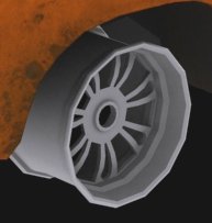
Mesh wheels allows you to do very nice wheels. It takes an Ogre3D mesh of a rim (the rim only, without the tire!). The mesh should be centered, and of the right size for the wheel you want to do: its outer diameter should be the same as the "rim_radius" parameter, and its width should be the same as the distance between node1 and node2. The other parameters are similar to the wheels section, though there are a few differences.
The side value should be l or r depending on the side of the wheel, and the final parameters are the mesh name and the material for the tire. The mapping of the texture should look something like this: 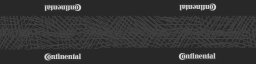
Here is an example picture of a rim mesh, as it should be modeled. The tire geometry is added dynamically afterward by the game, and will flex like a real tire.
meshwheels
;tire_radius, rim_radius, width, numrays, node1, node2, snode, braked, propulsed, arm,  mass,   spring, damping, side,               meshname         material
0.35,       0.21,   0.5,      14,    32,    33,    34,      1,         1,  18, 200.0, 300000.0,  2000.0,    l, dodgechargerwheel.mesh dodgechargerband
0.35,       0.21,   0.5,      14,    34,    35,    33,      1,         1,  26, 200.0, 300000.0,  2000.0,    r, dodgechargerwheel.mesh dodgechargerband
0.35,       0.21,   0.5,      14,    44,    45,  9999,      1,         0,  53, 200.0, 350000.0,  2000.0,    l, dodgechargerwheel.mesh dodgechargerband
0.35,       0.21,   0.5,      14,    46,    47,  9999,      1,         0,  50, 200.0, 350000.0,  2000.0,    r, dodgechargerwheel.mesh dodgechargerband
Meshwheels2
This section works exactly the same way as meshwheels, except one difference.
The tread of the wheel you generate does use the meshwheels section spring and damping ratios while the rim will use the ones from the set_beam_defaults.
It enables you to make quite soft and flexing wheels, which have a lot lateral grip and are very reliable and predictable in comparison to normal meshwheels.
Very useful for flex body tires, since the nodeflip-bug is mostly gone with this used the right way.
Use set_beam_defaults. that make sense for rims (high spring, low damping) while the tires itself can be soft and have high damping values:
set_beam_defaults 700000, 350, 60000000, 80000000
;set_beam_defaults for the rim

meshwheels2
;tire_radius, rim_radius, width, numrays, node1, node2, snode, braked, propulsed, arm,  mass,  tirespring,   tiredamping, side, meshname    material
0.660,      0.315, 0.375,      12,    27,    26,    38,      4,         1,  22, 100.0,    150000.0,        1500.0,    r, my-rim.mesh my-tire-material
Flexbodywheels
This section works exactly the same way then meshwheels2, except 2 differences:
There is a contactive rim generated and you can place a tire mesh which is converted to a flexbody by RoR.
For now, the rim mesh is a prop. Might be upgraded to flexbody later.
This one has complete new tire physics, so for now, happy testing, please give feedback.
set_beam_defaults 100000, 350, 60000000, 80000000
flexbodywheels
;radius, rimradius, width, rays, n1, n2, ref-n, braked, propulsed, force-n, weight, tire-spring, tire-damp, rim-spring, rim-damp, rim-orientation,           rim-mesh            tire-mesh
0.50,     0.300, 0.300,   16, 13, 11,  9999,      1,         1,      19,   92.5,      4500.0,     300.0,    3000000,      350,               r, testtruck-rim.mesh testtruck-wheel.mesh
Shocks
Shocks can be seen as tunable beams, useful for suspensions.
- node_1: Node number/name The node where the shock starts.
- node_2: Node number/name The node where the shock ends.
- spring_rate: Real number The 'stiffness' of the shock. The higher the value, the less the shock will move for a given bump.
- damping: Real number The 'resistance to motion' of the shock. The best value is given by this equation: [ 2 * sqrt(suspended_mass * spring_rate) ]
- max_contraction: Real number The shortest length the shock can be, as a proportion of its original length.
0means the shock will not be able to contract at all,1will let it contract all the way to zero length. If the shock tries to shorten more than this value allows, it will become as rigid as a normal beam. - max_extension: Real number The longest length a shock can be, as a proportion of its original length.
0means the shock will not be able to extend at all.1means the shock will be able to double its length. Higher values allow for longer extension. - precompression: Real number Changes compression or extension of the suspension when the truck spawns. This can be used to "level" the suspension of a truck if it sags in game. The default value is
1.0. - options (optional): String, default = no options (shock is visible)
i: This shock is invisible (default is visible).lOR L: Stability active suspension for left side.rOR R: Stability active suspension for right side.n: Placeholder. Does nothing, parser ignores it silently.
shocks
;critical damping=2*sqrt(mass*spring)
;id1, id2, spring, damping, shortbound, longbound, precomp, options
36,   6, 200000,   10000,        0.3,       0.3,     1.0
37,   8, 200000,   10000,        0.3,       0.3,     1.0,       l
38,   2, 200000,   10000,        0.3,       0.3,     1.0,       r
Shocks2
Shocks can be seen as tunable beams, useful for suspensions.
Parameters:
- node_1: Node number/name The node where the shock starts.
- node_2: Node number/name The node where the shock ends.
- spring_in_rate: Real number The 'stiffness' of the shock, applied when the shock is compressing. The higher the value, the less the shock will move for a given bump.
- damping_in_rate: Real number The 'resistance to motion' of the shock, applied when the shock is compressing. The best value is given by this equation: [ 2 * sqrt(suspended_mass * spring_rate) ]
- spring_in_progression_factor: Real number Progression factor for spring_in_rate. A value of
0disables this option. 1...x as multipliers, example: [ maximum springrate == springrate + (factor*springrate) ] - damping_in_progression_factor: Real number Progression factor for damp_in_rate.
0= disabled, 1...x as multipliers, example:[ maximum dampingrate == springrate + (factor*dampingrate) ] - spring_out_rate: Real number The 'stiffness' of the shock, applied when the shock is extending. The higher the value, the less the shock will move for a given bump.
- damping_out_rate: Real number The 'resistance to motion' of the shock, applied when the shock is extending. The best value is given by this equation: [ 2 * sqrt(suspended_mass * spring_rate) ]
- spring_out_progression_factor: Real number Progression factor for spring_out_rate. A value of
0disables this option. 1...x as multipliers, example: [ maximum springrate == springrate + (factor*springrate) ] - damping_out_progression_factor: Real number Progression factor for damp_out_rate.
0= disabled, 1...x as multipliers, example:[ maximum dampingrate == springrate + (factor*dampingrate) ] - max_contraction: Real number The shortest length the shock can be, as a proportion of its original length.
0means the shock will not be able to contract at all,1will let it contract all the way to zero length. If the shock tries to shorten more than this value allows, it will become as rigid as a normal beam. - max_extension: Real number The longest length a shock can be, as a proportion of its original length.
0means the shock will not be able to extend at all.1means the shock will be able to double its length. Higher values allow for longer extension. - precompression: Real number Changes compression or extension of the suspension when the truck spawns. This can be used to "level" the suspension of a truck if it sags in game. The default value is
1.0. - options (optional): String, default = no options (shock is visible)
i: This shock is invisible (default is visible).s: soft bump boundaries, use when shocks reach limiters too often and "jumprebound" (default is hard bump boundaries)m: metric values for shortbound/longbound applying to the length of the beamM: Absolute metric values for shortbound/longbound, settings apply without regarding to the original length of the beam. Use with caution, checkRoR.logfor errors.
IMPORTANT:
- shocks2 needs at least 1500+ as a minimum damping value when using them as inbound/outbound only. (When your shocks2 truck bottoms out at spawn, damping is too low (or the springs don't support the weight of the truck)
- soft bump shocks need some boundary limit ( 5%+ ) to work proper as soft bump boundaries.
- You will find any errors in the
RoR.logregarding to wrong values in 'M' setting or any other shock values.
shocks2
;invisible softbump shock, high value progressive for inbound, linear low values for outbound
;node1, node2, springin, dampin, progspringin, progdampin, springout, dampout, progspringout, progdampout, shortbound, longbound, precomp, options
45,    80,    22000,   2000,            5,          5,      2000,    1500,             0,           0,        0.8,       0.1,       1,      is

;visible hardbump shock, high value progressive for inbound and outbound, boundaries apply metric in meters
;node1, node2, springin, dampin, progspringin, progdampin, springout, dampout, progspringout, progdampout, shortbound, longbound, precomp, options
45,    80,    22000,   2000,           15,         10,      22000,    2000,           15,          10,        0.5,       0.5,       1,       m

;visible hardbump shock, high value progressive inbound only shock, boundaries apply metric as absolute values in meters
;node1, node2, springin, dampin, progspringin, progdampin, springout, dampout, progspringout, progdampout, shortbound, longbound, precomp, options
45,    80,    22000,   2000,            5,          5,          0,       0,            0,           0,        0.2,       2.5,       1,       M
Shockswapping help:
This is an example how to get started with replacing shocks with shocks2. In this example, the shocks2 have exactly the same functionality then the original shocks. After adding the shocks2 delete the old shock and you are fine to tune/tweak your truck.
shocks
;id1, id2, spring, damping, shortbound, longbound, precomp, options
36,   6, 200000,   10000,        0.3,       0.3,     1.0

shocks2
;node1, node2, springin, dampin, progspringin, progdampin, springout, dampout, progspringout, progdampout, shortbound, longbound, precomp, options
36,     6,   200000,  10000,            0,          0,    200000,   10000,             0,           0,        0.3,       0.3,     1.0
Shocks3
[ Version 2020.01+ ] Shocks can be seen as tunable beams, useful for suspensions.
Parameters:
- node_1: Node number/name The node where the shock starts.
- node_2: Node number/name The node where the shock ends.
- spring_in_rate: Real number The 'stiffness' of the shock, applied when the shock is compressing. The higher the value, the less the shock will move for a given bump.
- damping_in_rate: Real number The 'resistance to motion' of the shock, applied when the shock is compressing. The best value is given by this equation: [ 2 * sqrt(suspended_mass * spring_rate) ]
- damp_in_slow: Real number Damping factor for compression speeds below split_vel_in, example: [ damping == damp_in * damp_in_slow * vel ]
- split_vel_in: Real number Velocity threshold for the slow / fast compression speed
- damp_in_fast: Real number Damping factor for compression speeds above split_vel_in, example:[ damping == damp_ing * damp_in_slow * split_vel_ing + damp_in * damp_in_fast * (vel - split_vel_in) ]
- spring_out_rate: Real number The 'stiffness' of the shock, applied when the shock is extending. The higher the value, the less the shock will move for a given bump.
- damping_out_rate: Real number The 'resistance to motion' of the shock, applied when the shock is extending. The best value is given by this equation: [ 2 * sqrt(suspended_mass * spring_rate) ]
- damp_out_slow: Real number Damping factor for extension speeds below split_vel_out, example: [ damping == damp_out * damp_out_slow * vel ]
- split_vel_out: Real number Velocity threshold for the slow / fast extension speed
- damp_out_fast: Real number Damping factor for extension speeds above split_vel_out, example:[ damping == damp_out * damp_out_slow * split_vel_out + damp_out * damp_out_fast * (vel - split_vel_out) ]
- max_contraction: Real number The shortest length the shock can be, as a proportion of its original length.
0means the shock will not be able to contract at all,1will let it contract all the way to zero length. If the shock tries to shorten more than this value allows, it will become as rigid as a normal beam. - max_extension: Real number The longest length a shock can be, as a proportion of its original length.
0means the shock will not be able to extend at all.1means the shock will be able to double its length. Higher values allow for longer extension. - precompression: Real number Changes compression or extension of the suspension when the truck spawns. This can be used to "level" the suspension of a truck if it sags in game. The default value is
1.0. - options (optional): String, default = no options (shock is visible)
i: This shock is invisible (default is visible).m: metric values for shortbound/longbound applying to the length of the beamM: Absolute metric values for shortbound/longbound, settings apply without regarding to the original length of the beam. Use with caution, checkRoR.logfor errors.
shocks3
;node1, node2, springin(N/m), dampin(N/m/s), slowdampin, splitin(m/s), fastdampin, springout(N/m), dampout(N/m/s), slowdampout, splitout(m/s), fastdampout, shortbound, longbound, precomp, options
46, 55, 65000, 5800, 0.5, 1.2, 0.2, 65000, 1080, 0.5, 1.2, 0.2, 0.62, 0.00, 1.2, n
Hydros
The hydros section is concerned only with the steering actuators! They are beams which change their length depending on the steering of the truck. Hydros can use inertia.
Parameters:
- node_1: Node name or number The node where the hydro starts.
- node_2: Node name or number The node where the hydro ends.
- lengthening_factor: Real number How much the hydro extends or contracts when a steering key is pressed (expressed as a proportion of the original length). Positive values extend when steering left and contract when steering right. Negative values do the reverse.
- options (optional) String, default = no options (hydro is visible)
i: Makes the hydro invisibles: (Land vehicles) Disables the hydro at high speed (as seen sometimes with rear steering axles on large trucks)a: [ Version 0.36+ ] (Airplanes) This hydro is commanded by aileron input.r: [ Version 0.36+ ] (Airplanes) This hydro is commanded by rudder input.e: [ Version 0.36+ ] (Airplanes) This hydro is commanded by elevator input.u: [ Version 0.36+ ] (Airplanes) This hydro is commanded by the combination of aileron input and elevator input.v: [ Version 0.36+ ] (Airplanes) This hydro is commanded by the combination of inverse aileron input and elevator input.x: [ Version 0.36+ ] (Airplanes) This hydro is commanded by the combination of aileron input and rudder input.y: [ Version 0.36+ ] (Airplanes) This hydro is commanded by the combination of inverse aileron input and rudder input.g: [ Version 0.36+ ] (Airplanes) This hydro is commanded by the combination of elevator input and rudder input.h: [ Version 0.36+ ] (Airplanes) This hydro is commanded by the combination of inverse elevator input and rudder input.
- start_delay (optional): Real number Inertia.
- stop_delay (optional): Real number Inertia.
- start_function (optional): String Inertia.
- stop_function (optional): String Inertia.
hydros
;node1, node2, factor, options
43,   37,    -0.2
45,   37,     0.2
46,   36,     0.2,       s
48,   36,    -0.2,       s
Animators
The animator section concerns only Animators referring to game data! They are beams which change their length depending on the variables of the simulation.
The parameters are:
- Node 1 - Node name or number The node where the animator starts. Required
- Node 2 - Node name or number The node where the animator ends. Required.
- lengthening factor - Real number A coefficient which specifies how much the animator moves. Required.
- Option string - String Required
Options:
vis- This creates a visible animator. ( It's not necessarily needed, but can help users read the truck file.)inv- This creates an invisible animator.airspeed- This animator extends or contracts with the actual speed (not speedometer indicated speed) for any vehicle.vvi- This animator extends or contracts with the vehicle's vertical velocity.altimeter100k- This animator extends or contracts with the vehicle's altitude up to 100,000 feet.altimeter10k- This animator extends or contracts with the vehicle's altitude up to 10,000 feet, at which point it will revert back to its original length.altimeter1k- This animator extends or contracts with the vehicle's altitude up to 1,000 feet, at which point it will revert back to its original length. These three animators can be used to create altimeters with three needles or similar objects, though for those small applications it is usually recommended that Add_animation be used.aoa- This animator extends or contracts with the dashboard's angle of attack.flap- This animator extends or contracts with the flap setting on the vehicle.airbrake- This animator extends or contracts with the airbrake setting on the vehicle.roll- This animator extends or contracts with the vehicle's roll. It will flip at 180 degrees roll to -180 degrees roll. This option can be used for an automatic trim feature.pitch- This animator extends or contracts with the vehicle's pitch. It will flip back at 180 degrees pitch to -180 degrees pitch. This option can be used for an automatic trim feature.throttle1- This animator extends or contracts with the throttle setting of an aircraft's first engine. This option can be used for thruster mechanics. Valid sources include throttle1, throttle2, etc. etc. up to throttle8.rpm1- This animator extends or contracts with the RPM of an aircraft's first engine. This option can be used for thruster mechanics. Valid sources include rpm1, rpm2, etc. etc. up to rpm8.aerotorq1- This animator extends or contracts with the torque of an aircraft's first engine. Note that this only works for propeller engines, because torque is not applicable to jets. Valid sources include aerotorq1, aerotorq2, etc. etc. up to aerotorq8.aeropit1- This animator extends or contracts with the pitch of an aircraft's first engine. Note that this only makes sense with propeller engines, pitch is not applicable to jets. Valid sources include aeropit1, aeropit2, etc. etc. up to aerotorq8.aerostatus1- This animator extends with the On/Off/Fire status of an aircraft's first engine. Valid sources include aerostatus1, aerostatus2, etc. etc. up to aerostatus8.brakes- This animator extends or contracts with the vehicle's brake status.accel- This animator extends or contracts with the vehicle's accelerator status.clutch- This animator extends or contracts with the vehicle's clutch status.speedo- This animator extends or contracts with the speedometer indication. It scales with the guisetting speedometer. (It is best to use it even if there is no custom overlay dashboard; it simplifies the adjustment a lot.)tacho- This animator extends or contracts with the vehicle's RPM. It scales with guisetting tachometer. (It is best use it even if there is no custom overlay dashboard; simplifies the adjustment a lot.)turbo- This animator extends or contracts with the vehicle's turbocharger PSI.parking- This animator extends or contracts with the vehicle's parking brake status.shifterman1- H-shift left right animator (Reverse | 1-2 | 3-4 | 5-6...11-12as positions, scales with engine settings (maxGear)shifterman2- H-shift forth/back animatorReverse-2-6-8-10-12 | 1-3-5-7-9-11as positionssequential- sequential shift animator ( i.e for tiptronic or wheel shift pedals), can be used for commands too ( no settable limits then )shifterlin- for auto transmission animations or gearselect indicatorstorque- animator to simulate engine torque, useful in addition to wheel nodearmsdifflock- This animator extends or contracts with the difflock status of the truck (It only works when differentials are present in the truck.)rudderboat- This animator extends or contracts with the steering hydro on boats.throttleboat- This animator extends or contracts with the throttle status on boats.shortlimit- Adds shortbound movement limit to the animator, needs to be followed by a valid number. Limits are calculated in percentage like shocks. [ Version 0.38.24+ ]longlimit- Adds longbound movement limit to the animator, needs to be followed by a valid number. Limits are calculated in percentage like shocks. [ Version 0.38.24+ ]
All options need to be connected by an vertical bar |, please refer to the example below.
You can stack multiple options (like: airpseed | vvi | inv), but it is not recommended and may result in weird behaviors.
All animators are scaled to a maximum of -1/+1 as default coefficient, use the ratio setting to get the movement you want.
Speed or force of the animators is NOT settable, though you can alter movement speed just with simple lever mechanics.
The longer the lever arm, the slower the node will move. To tune your torque-animator to the needs of the truck, let it just work against a stiff shocks2. The harder you make the shock, the more engine-rpm torque effect you get.
Animators can use set_inertia_defaults. Inertia helps a lot to smooth instant movement like with shifters or airbrakes.
animators
;node1, node2, factor, options
32,    26,   0.09, shifterlin | inv
 5,    27,   0.10, accel | inv
 5,    28,   0.10, brake | inv
 5,    29,   0.10, clutch | inv
36,    41,  -0.40, speedo | inv
;this one is visible
49,     3,  -0.90, torque | vis
;this one is visible and has a short and a longbound limit
49,     3,  -0.25, roll | vis | shortlimit: 0.02 | longlimit: 0.05
Behavior
These sections define behaviors for the vehicle, like command-operated hydraulics and modifications to how beams behave.
Commands
The commands section describes the "real" hydros, that is, those you command with the function keys. They are like beams, but their length varies depending with the function keys you press. The parameters are:
- Node 1: Node number/name; The node where the command beam starts.
- Node 2: Node number/name; The node where the command beam ends.
- Rate of extension/contraction: Real number How fast the command beam moves.
- Maximum contraction: Real number The shortest length that the command beam will try to be, as a proportion of its initial length.
- Maximum extension: Real number The longest length the command beam will try to be, as a proportion of its initial length.
- Contraction key: Function key code (decimal number) A number representing the function key used to control the command beam. More than one can be controlled with the same key. (See below for the keymap.)
- Extension key: Function key code (decimal number) The key used to extend the command beam.
- Option flag (optional): Single character
i: Makes the command beam invisible.r: Makes the command behave like a rope or a winch (no compression strength).c: Makes the command beam auto-center: It will automatically return it to its starting position when a lengthening/shortening key is released.n: Placeholder, does nothing (useful as filler when you need to specify description)
- Description (optional): String A text description that tells the user what the command beam does when the it is activated. This is shown by pressing
CTRL+Tingame. There is no need to put a key in front of the text (like F1:_do_something) this will be done automatically! Writing "hide" will hide the command from the "t-screen".
commands
;id1, id2, rate, short, long, keys, keyl, options description
10,  91,  0.1,   1.0,    7,    1,    2,       i Death_machine
12,  93,  0.1,   1.0,    7,    1,    2,       i
14,  90,  0.1,   1.0,    7,    1,    2
16,  92,  0.1,   1.0,    7,    1,    2
114, 122,  0.2,   1.0,   19,    3,    4
115, 123,  0.2,   1.0,   19,    3,    4,       n Happy_butterfly_wings
126, 132,  0.1,   0.1,  1.0,    5,    6,       r
This is the default keymap:
- 1 =
F1 - 2 =
F2 - 3 =
F3
etc. etc.
- 12 =
F12 - 13 =
CTRL+F1 - 14 =
CTRL+F2
etc. etc.
- 24 =
CTRL+F12 - 25 =
ALT+F1 - 26 =
ALT+F2
etc. etc.
- 36 =
ALT+F12 - 37 =
CTRL+ALT+F1 - 38 =
CTRL+ALT+F2
etc. etc.
- 46 =
CTRL+ALT+F10
Since RoR 0.4.0.5 it is possible to use up to 84 commands. The keymap changed because of that:
- 1 =
F1 - 2 =
F2 - 3 =
F3
etc. etc.
- 12 =
F12 - 13 =
CTRL+F1 - 14 =
CTRL+F2
etc. etc.
- 24 =
CTRL+F12 - 25 =
SHIFT+F1 - 26 =
SHIFT+F2
etc. etc.
- 36 =
SHIFT+F12 - 37 =
ALT+F1 - 38 =
ALT+F2
etc. etc.
- 46 =
ALT+F10 - 49 =
CTRL+SHIFT+F1 - 50 =
CTRL+SHIFT+F2
etc. etc.
- 59 =
CTRL+SHIFT+F11 - 61 =
CTRL+ALT+F1 - 62 =
CTRL+ALT+F2
etc. etc.
- 72 =
CTRL+ALT+F12 - 73 =
CTRL+SHIFT+ALT+F1 - 74 =
CTRL+SHIFT+ALT+F2
etc. etc
- 84 =
CTRL+SHIFT+ALT+F12
Note that some keymapped commands are by default assigned to Windows commands.. i.e. ALT+F4 closes the active window (in this case the RoR render window). It is best to avoid using those buttons if at all possible.
If you hold F4 then hold/press ALT, the window should stay open and the command will work.
Commands2
Improved commands.
Commands are beams which contract and extend when player presses the corresponding key combination.
Since [ Version 0.36.2 ] you can specify an inertia function for your command. This reduces the swing of commands since they will operate smoothly with inertia.
The parameters are:
- Node 1: Node number/name; The node where the command beam starts.
- Node 2: Node number/name; The node where the command beam ends.
- Shortening rate: Positive real number; How fast the command beam shortens.
- Lengthening rate: Positive real number; How fast the command beam lengthens.
- Maximum contraction: Positive real number; The shortest length that the command beam will try to be, as a proportion of its initial length.
- Maximum extension: Positive real number; The longest length the command beam will try to be, as a proportion of its initial length.
- Shortening key: Key code (decimal number); A number representing the function key needed to compress the command beam. More than one can be controlled with the same key. (see above for keymap)
- Lengthening key: Key code (decimal number); The key used to extend the command beam.
- Option flag(s) (optional):
n: Filler option, does nothing.i: Makes the command beam invisible.r: Makes the command beam behave like a rope or a winch.c: Makes the command beam auto-center: It will automatically return it to its starting position when a lengthening/shortening key is released.f: Stops the command moving faster when engine revs increase.p: Activates press-once functionality: A single press of a shortening/lengthening key will lengthen/shorten the command beam as much as possible. A second keypress of the key which started the command moving stops the automatic movement.o: is likep, but it will stop in the center position.
- Description (optional): Placeholder = underscore '_' A text description that tells the user what the command beam does when it is activated. This is shown by pressing
CTRL+Tingame. There is no need to put a key in front of the text (like F1:_do_something) this will be done automatically! Writing "hide" will hide the command from the "t-screen". - Inertia: Start delay factor (optional): [ Version 0.36.2+ ]; Positive real number; The delay upon command start. Note this isn't time in seconds, but are a factor (the lower the value, the more inertia there is)
- Inertia: Stop delay factor (optional): [ Version 0.36.2+ ]; Positive real number; The delay upon command stop. Note this isn't time in seconds, but are a factor (the lower the value, the more inertia there is)
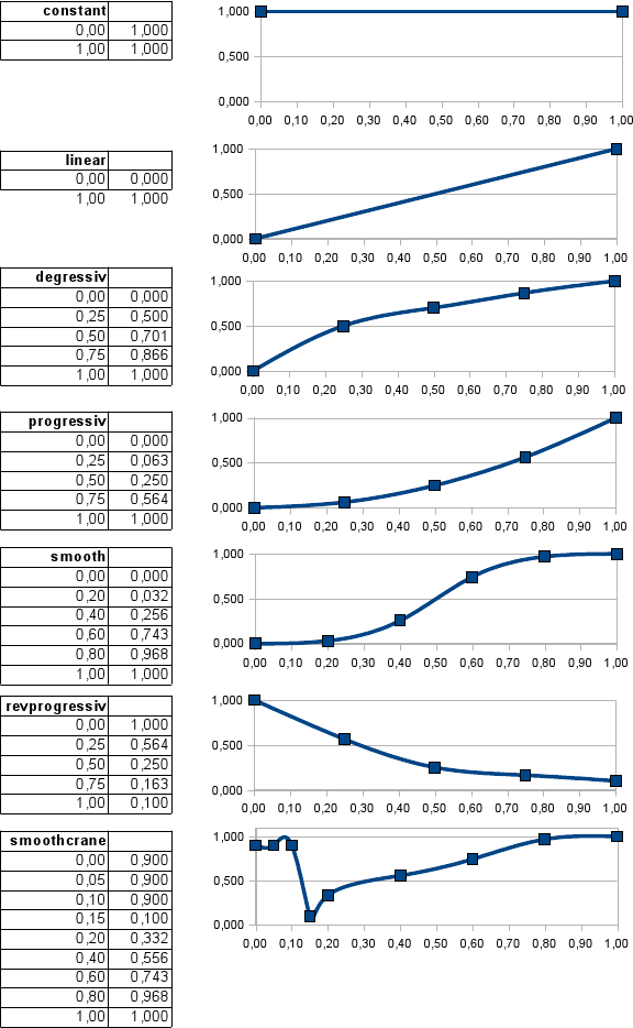
- Inertia: Start function (optional): [ Version 0.36.2+ ]; String; Specifies what spline should be used for start. See diagram below.
- Inertia: Stop function (optional): [ Version 0.36.2+ ]; String; Specifies what spline should be used for stop. See diagram below.
- Affects engine? (optional): [ Version 0.4.0.5+ ]; Positive real number; default = 1.0; 0 means that moving this command won't affect engine RPM, so it is independent. Value larger than 0 specifies how much engine power will be needed for this command to move.
- Needs engine? (optional): [ Version 0.4.0.5+ ]; Boolean; default = true; value of "true" means that the command only works with a running engine. "False" means engine is not needed.
commands2
;id1, id2, rateShort, rateLong, short, long, keys, keyl, options Description
61, 113,       0.1,      0.5,   1.0,    4,    1,    2,      of
62, 112,       0.1,      0.5,   1.0,    4,    1,    2,     onf desc

commands2
;id1, id2, rateShort, rateLong, short, long, keyS, keyL, options      description startDelay, stopDelay, startFunction  stopFunction
115, 123,      0.10,     0.10,  1.00, 19.0,    3,    4,       n      First_Joint        0.5,       0.5,   smoothcrane revprogressiv
127, 133,      0.10,     0.10,  1.00, 10.5,    5,    6,       n     Second_Joint        0.7,       0.5,   smoothcrane revprogressiv
137, 147,      0.10,     0.10,  1.00, 10.5,    7,    8,       n      Third_Joint        0.7,       0.5,   smoothcrane revprogressiv
143, 148,      0.05,     0.05,  0.50,  2.0,    9,   10,       n  Extremity_Joint        0.7,       0.5,   smoothcrane revprogressiv

commands2
;id1, id2, rateShort, rateLong, short, long, keyS, keyL, options      description startDelay, stopDelay, startFunction  stopFunction affectEngine needsEngine
115, 123,      0.10,     0.10,  1.00, 19.0,    3,    4,       n      First_Joint        0.5,       0.5,   smoothcrane revprogressiv            0           1
127, 133,      0.10,     0.10,  1.00, 10.5,    5,    6,       n     Second_Joint        0.7,       0.5,   smoothcrane revprogressiv            0           0
137, 147,      0.10,     0.10,  1.00, 10.5,    7,    8,       n      Third_Joint        0.7,       0.5,   smoothcrane revprogressiv            1           1
143, 148,      0.05,     0.05,  0.50,  2.0,    9,   10,       n  Extremity_Joint        0.7,       0.5,   smoothcrane revprogressiv            1           0
Note: You may mix commands/commands2 sections, depending on what you want to use. Example:
commands2
;id1, id2, rateShort, rateLong, short, long, keyS, keyL, options description
61, 113,       0.1,      0.5,   1.0,    4,    1,    2,      of
62, 112,       0.1,      0.5,   1.0,    4,    1,    2,     onf Boom

commands
;id1, id2,      rate,           short, long, keyS, keyL, options description
116, 124,       0.1,             1.0,  2.6,    3,    4
117, 125,       0.1,             1.0,  2.6,    3,    4,       n Underlift

commands2
;id1, id2, rateShort, rateLong, short, long, keys, keyl, options Description
136, 116,       0.4,      4.4,   1.0,   10,    5,    6
136, 117,       0.4,      4.4,   1.0,   10,    5,    6
Set_inertia_defaults
This command will set the defaults for all following commands, hydros, animators and rotators.
- start_delay: Real number, default = -1.0. Entering value < 0 will reset all 4 values of this directive to defaults.
- stop_delay (optional): Real number, default = -1.0. Entering value < 0 will reset all 4 values of this directive to defaults.
- start_function (optional): Inertia function name, default = none.
- stop_function (optional): Inertia function name, default = none.
;set_inertia_defaults startDelay, stopDelay, startFunction  stopFunction
set_inertia_defaults         0.5,       0.5,   smoothcrane revprogressiv
...
set_inertia_defaults         0.7,       0.5,   smoothcrane revprogressiv
...
; reset:
set_inertia_defaults -1
NOTE: Both commas and spaces are accepted as delimiters between parameters.
Rotators
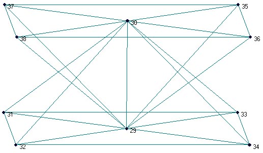
Rotators are alternate commands(hydros) that allows you to do turntables, like in the base of a rotating crane. They use 10 reference nodes:
- 2 nodes to define the axis of rotation
- 4 nodes (must be a square, centered with the axis) to define the baseplate
- 4 nodes (again, a square, centered with the axis) to define the rotating plate.
Then, in a similar way to commands, comes the rate of rotation, and the numbers of the left and right function keys.
New in [ Version 0.4+ ]
- start_delay. Real, default
0.0 - stop_delay. Real, default
0.0 - start_function.
- stop_function.
- engine_coupling. Real, default
1.0 - needs_engine. Boolean, default false
Rotators can use inertia.
The reference nodes for the baseplate and rotator plate must also match each other in order. (i.e. if you start at the front left for the base plate and work clockwise, do the same for the rotator plate!) See the example rotators code and attached picture. Both plates must be identical!
rotators
;axis1, axis2,   a1, a2, a3, a4,   b1, b2  b3, b4,   rate, keyleft, keyright, (Ver. 0.4+) start_delay, stop_delay, start_function, stop_function, engine_coupling, needs_engine
29,    30,   31, 32, 34, 33,   37, 38, 36, 35,    0.1,       1,        2,                       1,          1,         smooth,        smooth,             0.5,         true
Rotators2
Same as rotators section, but more options that allow lightweight rotators, rotator force setting and tolerance (anti jitter) setting and correct description parsing. Additional options:
- Force: the rotating power of the rotator, default is
10000000 - Tolerance: anti jitter setting for lightweight rotators, default is
0.0. Rise gently to make your rotator spawn and rotate stable if needed - Description: descriptive text visible in the t-screen
rotators2
;axis1, axis2,   a1, a2, a3, a4,   b1, b2  b3, b4,   rate, keyleft, keyright,   force, tolerance,               description, (Ver. 0.4+) start_delay, stop_delay, start_function, stop_function, engine_coupling, needs_engine
29,    30,   31, 32, 34, 33,   37, 38, 36, 35,    0.1,       1,        2, 1000000,     0.025, Superstructure_left/right,                       1,          1,         smooth,        smooth,             0.5,         true
Forwardcommands
Forwards the command keys pressed while riding a truck to loads in close proximity. It is used to remote control the commands of a load. The load must have the "importcommands" tag.
forwardcommands
In 0.4.0.5 and above it is possible to toggle forwardcommands on/off for the current beam object. The standard button assignment for this is CTRL+SHIFT+F.
Importcommands
Enables a load to receive command keys from a manned vehicle in close proximity. The controlling vehicle must have the "forwardcommands" tag. The load only receives the keys that are pressed by the player, it must contain a commands section. Commands section for loads is defined in the same manner as in manned trucks.
importcommands
In 0.4.0.5 and above it is possible to toggle importcommands on/off for the current beam object. The standard button assignment for this is CTRL+SHIFT+I.
Set_beam_defaults
This is not a section, but a self-contained line that can be inserted anywhere in the truck file. It changes all the beams (and the hydros and ropes) declared after this line. You can use this line many times to make different groups of beams that have different characteristics (e.g. stronger chassis, softer cab, etc.).
Parameters:
- Springiness: Real number; Default:
9000000; The overall stiffness of a beam. The higher the value the stiffer the beam. - Damping constant: Real number; Default:
12000; The resistance to motion of a beam. Higher values make the beam less likely to deform. - Deformation threshold constant: Real number; Default:
400000; The amount of force that must be applied to a beam before it will not return to its original length. The lower the value, the easier it is to deform. - Breaking threshold constant: Real number; Default:
1000000; The amount of force that must be applied to a beam before it will break. - Beam diameter: (optional); Real number; Default:
0.05(= 5cm) The visual size of a beam in meters. This setting only has a visual effect. Changing it does not modify how a truck will drive. - Beam material (optional); String; Default: tracks/beam; The material used to color the beam. It must be defined in a separate
.materialfile. - Plastic deformation coefficient: (optional); Real number in range:
0.0-1.0; Default:0.0; This defines how elastic the deformation of a beam is. It is explained in greater detail below.
To use default values without having to type the numbers, use -1 in each field. Example:
set_beam_defaults -1, -1, -1, -1
Or if you want to use the default values as a base:
set_beam_defaults 9000000, 12000, 400000, 1000000, 0.05, tracks/beam, 0.0
Beware: Excessive spring will result in an unstable chassis. Increasing the damping will help with this, but excessive damping will crash RoR. Higher chassis mass may mitigate that problem if applicable. If you create a light car, you may want to reduce the spring, damping and deformation values to match the real, softer frame of a car, and also increase stability.
Be aware that the current default values are "overspringy", or "underdamped" for stability reasons (that is why trucks often look too springy when they fall down a slope), but on softer designs you can correct this and have a better damping ratio. Missing beam textures may make RoR unstable. Example for a car:
;set_beam_defaults spring, damping, deform,  break, diameter, material
set_beam_defaults 3000000,   10000, 100000, 250000,     0.02, tracks/beamblack
If you want to keep a rigid chassis base and drivetrain, you can do:
beams
;base chassis and drivetrain with the default high-strength settings
1,2
2,3
...
3,4
;car body, softer setting
set_beam_defaults 3000000, 10000, 100000, 250000
5,6
6,7
...
;return to stronger defaults for the rest (e.g. hydros)
set_beam_defaults -1, -1, -1, -1
...
If you want to to make something deform well (like for flexbodies), use these settings for the beam group you want to deform together with the global enable_advanced_deformation option to unleash unlimited beam physics for best results in crash deformation:
;set_beam_defaults spring, damping, deform,  break, diameter,         material, deform_coef
set_beam_defaults 3000000,   10000, 100000, 250000,     0.02, tracks/beamblack,         0.9
The plastic deformation coefficient is 0.0 by default (elastic deformation). By setting it as property you can tune the related beam group to your needs.
For example, if a cube made of nodes and beams is crashed to a wall, then the placement of the nodes are displaced, altering the original shape to an irregular one.
This also affects the length of beams, if nodes are displaced, the beams may conform to a new shorter or longer length, and staying that way until another outside force is applied.
Valid values: 0.0 - 1.0, do not exceed that range! A plastic deformation coefficient setting of 0.0 is close to the original beam behavior of RoR 0.36.2 (quite elastic). 1.0 is close to the maximum plastic deformation you were able to reach with the former experimental enable_advanced_deformation patch.
Never use a break setting lower then a deform setting! This will result in a beam breaking instantly when it starts deforming!
Set_beam_defaults_scale
This is not a section, but a self-contained line that can be inserted anywhere in the truck file. It changes the scale of all following set_beam_defaults lines to a certain factor:
- Springiness - Scale: 0-1
- Damping constant - Scale: 0-1
- Deformation threshold constant - Scale: 0-1
- Breaking threshold constant - Scale: 0-1
The default is all 1 for all arguments.
set_beam_defaults_scale 1, 1, 1, 1
Example that scales spring to 50%:
set_beam_defaults_scale 0.5, 1, 1, 1
Take note:
- Unlike
set_beam_defaults, you must always give all four arguments. Its not possible to leave some out. - Any
set_beam_defaultsline that is scaled will output a line toRoR.logsayingDue to using set_beam_defaults_scale, this set_beam_defaults was interpreted as ...
Set_node_defaults
This is a directive which affects all nodes (including wheel and camera nodes) declared on lines below it. You can use this line many times to make different groups of nodes that have different characteristics (e.g. more grip for wheels, more surface drag for chassis nodes, etc.).
The parameters are:
- loadweight: Real number; Default:
0.0; The default loadweight mass applied to a node. Will be overridden by a per node definition (the optionl). Minimass calculation is unaffected. - friction: Real number; Default:
1.0; The amount to multiply the node's friction by. A setting of2will double the friction; a setting of0will create a frictionless node. - volume: Real number; Default:
1.0; The amount to multiply the node's buoyancy. A setting of2will double the buoyancy; a setting of0will create a non-buoyant node. This only applies when the node is in a fluid. - surface: Real number; Default:
1.0; The amount to multiply the node's surface by. A setting of2will double the surface; a setting of0will create a node with no surface. This only applies when the node is in a fluid. - options: (optional); Options string; Set any node-option property as default. You do not need to set the
lproperty if a default loadweight is set.
Important: Buoyancy volume and drag surface settings only have effect on fluids defined in ground_models.cfg (mud definitions), so right now they do not work with the standard RoR Water.
To use default values without having to type the numbers, use "-1" in each field. For example:
set_node_defaults -1, -1, -1, -1
Beware: Excessive friction, surface and volume will result in an unstable node/beam structure when driving in mud. If your wheels/truck explodes when driving from solid ground onto mud, lower the friction and/or volume setting. If a wheel cracks while in the mud, lower the volume and/or the surface setting.
Syntax is set_node_defaults loadweight, traction, buoyancy, surface
Mud tire example, unloaded, increased traction, higher buoyancy, higher drag surface and set to extra per node buoyancy:
set_node_defaults -1, 1.1, 5, 1.25, b
Chassis, loaded with 5 kg per node, reduced traction, no buoyancy, higher drag surface:
set_node_defaults 5, 0.5, 0, 2
Tracks example, high traction, low buoyancy, low surface, loaded with 50 kg per node:
set_node_defaults 50, 1.2, 0.3, 0.5
Steam boat paddlewheel, loaded with 75 kg per node, no traction, no buoyancy, high drag surface:
set_node_defaults 75, 0, 0, 3
Contactless with default settings:
set_node_defaults -1, -1, -1, -1, c
The new L node option will help to understand and use set_node_defaults, p node option will boost fps even with tracked vehicles on slower computers. See: nodes
Enable_advanced_deformation
This is not a section, but a self-contained line that can be inserted anywhere in the truck file. It changes the general beams deformation physics.
Use this only once per truck file, it's a general activation and setting of advanced beam physics . Its recommended to place the enable_advanced_deformation before the first beams section in your truck-file.
Truck file syntax:
enable_advanced_deformation
This will remove any limit and thresholds from the set_beam_defaults processing. Its recommended to use it for the development of properly deforming flexbody node\beam structures.
Rollon
NOTE: This directive has no effect as of version 0.39.5+
Enables collision between wheels and the contactable textured surfaces of a truck.
rollon
Contacters
The contacters section lists the nodes that may contact with cab triangles. This concerns only contacts with other trucks or loads. You can easily omit this section at first.
contacters
34
18
20
22
24
26
28
30
32
Triggers
Triggers are special beams which trigger user-specified events when extended/contracted to a given bound. They have no physics attributes and can extend indefinitely.
Parameters:
- Node 1: Node number/name; The node where the trigger beam starts.
- Node 2: Node number/name; The node where the trigger beam ends.
- contraction_trigger_limit: Real number; The length when the shortkey command gets triggered
- extension_trigger_limit: Real number; The length when the longkey command gets triggered
- shortbound_trigger_action: Positive or negative Decimal number; On normal triggers without a special option this represents the command key to be triggered at shortbound (1 - 48 [ Version 0.4.0.7+ ] 1 - 84). For other trigger types, look below.
- longbound_trigger_action: Positive or negative Decimal number; On normal triggers without a special option this represents the command key to be triggered at longbound (1 - 48 [ Version 0.4.0.7+ ] 1 - 84). For other trigger types, look below.
- options (optional): String
i: Makes the trigger beam invisiblec: Set the boundary calculation to command-style, just for conveniencex: Set the trigger to disabled on startup ( default =enabled), will get useless after first activation by a triggerblockerb: Blocks other commandkeys, shortkey at shortbound, longkey at longbound. If longkey is set to-1, shortkey will get blocked at short and at longbound. It does not block of manual user inputs, just triggers.B: Blocks other triggers when triggered, a number in shortkey represent the number of triggers to block at shortbound , a number in longkey the number of triggers to release at longbound.A: [ Version 0.38.23+ ] Same as the BlockerB, but inverted activation. Will block while between shotbound and longbound a number of triggers (shortkey) and release if not (longkey).s: Switches commandnumbers when triggered set in shortkey and longkey. Good to build wipers or similar, see examplesh: [ Version 0.38.26+ ] You can use triggers to lock or unlock hookgroups ( only hookgroups <=-3); Unlocks hookgroups shortkey at shortbound and hookgroup longkey at longbound.H: [ Version 0.38.26+ ] You can use triggers to lock or unlock hookgroups ( only hookgroups <=-3); Locks hookgroups shortkey at shortbound and hookgroup longkey at longbound.t: [ Version 0.4.0.7+ ] Continuous trigger, delivers a value of0below and at shortbound, a value of1over and at longbound. Between these boundaries, this trigger will deliver a value between0and1(linear), depending on the current position. See "engine trigger" for details on how to use this.E: [ Version 0.4.0.7+ ] Engine trigger. This trigger gives you control over various vehicle driving functions. It is recommended to use this in combination with at-trigger to get precise, continuous control. Works as follows:- ''' (remapped) shortbound_trigger_action''': Positive decimal number Takes the number of the engine to be controlled, starting with
0. As RoR only supports one engine per vehicle at the moment, always put0here. - ''' (remapped) longbound_trigger_action''': Positive decimal number Takes the number of the function you want to control:
0: Clutch1: Brake2: Accelerator3: RPM Control (not available at the moment)4: Shift Up (use no "t"-trigger here). Will shift up on short and longbound.5: Shift Down (use no "t"-trigger here). Will shift down on short and longbound.
- ''' (remapped) shortbound_trigger_action''': Positive decimal number Takes the number of the engine to be controlled, starting with
- boundary_timer (optional): Positive real number; default =
1.0; Represents the time a boundarycheck is disabled for trigger switches ( options) to avoid lockup.
triggers
;id1, id2,  short,  long, shortbound action, longbound action, options
; a trigger between node 11 and 109 triggering commandkey 13 ( ctrl-F1) while in shortbound -10% of original length
; and commandkey 14 (ctrl-F2) when in longbound +10% of original length
11, 109,  0.100,  0.100,      13,      14

; a trigger between using command boundaries, does exactly the same then the one above
11, 109,  0.900,  1.100,      13,      14, c

; a trigger blocked at startup, needs to be released by a triggerblocker once to work as a normal trigger,
; good for simple robotic programming
11, 109,  0.900,  1.100,      13,      14, cx

; special case triggers: cmdkeyblocker, triggerblocker, triggerswitch
; a commandkeyblocker blocking commandkeys when active, 15 (ctrl-F3) at shortbound and  16 (ctrl-F4) at longbound.
11, 109,  0.900,  1.100,      15,      16, cb

; a commandkeyblocker blocking one commandkey when active, 15 (ctrl-F3) at shortbound and  at longbound.
11, 109,  0.900,  1.100,      15,      -1, cb

; a triggerblocker blocking the following triggers from checking, blocking 5 at shortbound and releasing 4 at longbound,
; Most times it will block and release the same amount of triggers, but its good for robotics programming to set separate amounts in some cases.
11, 109,  0.900,  1.100,       5,       4, cB

; a triggerswitch switching commandkeys when active, also for user inputs,  will switch F1 to F2 and vice versa every time it hits short or longbound,
;  release timer is set to 1 second by default, before it can be triggered again.
11, 109,  0.900,  1.100,       1,       2, cs

; a triggerswitch switching commandkeys when active, also for user inputs,  will switch F1 to F2 and vice versa every time it hits short or longbound,
; release timer is set to 3 seconds.
11, 109,  0.900,  1.100,       1,       2, cs 3.0

;  an engine trigger, controlling the accelerator (option "2") of engine nr. 0. Will give zero throttle in initial position (shortbound), full throttle at longbound, and a linear crossover in between.
11, 109,  1.000,  1.500,       0,       2, ctE
Lockgroups
This section defines lockgroups for nodes. It has to be AFTER the nodes section
Lockgroup Default = -1, all nodes can be locked by standard hooks with no special lockgroup set
Important:
- Special lockgroup:
9999skip the node from any locking attempts - POSITIVE lockgroups are free to use, the negative range is reserved for RoR built in standard lock-setups.
lockgroups
;lockgroup,  nodeIDs
; node 5 added to lockgroup 1
1,        5
;nodes 6, 7, 9 added to lockgroup 2
2,  7, 6, 9
Performance boost option (needs to be BEFORE the nodes section):
lockgroup_default_nolock
This will set all nodes to 9999 (deny locking) of the truck by default.
Any lockgroups defined later in the truck will override this setting for the specified node.
Allows you to define exactly where standard hooks can lock to your truck and boost performance a lot when autolock hooks are used.
Its recommended to use this option as default.
Hooks
This section defines special options for hooknodes setup in the nodes section. It has to be placed after the nodes section.
- id: A node number to identify the hooknode the options apply to. The node number needs to exist and it has to be a hooknode with option
h - options: no order needed, just place what you need, here is a list of possible options:
hookrange:The range a hook scans for a valid node to lock to, Default:0.4speedcoef:The speed a hook pulls the node to lock into locking position. Default:1.0maxforce:The force limit where a locking attempt is canceled. Default:100000000.0hookgroup:The hookgroup a hook belongs to. Standard hook:-1(Default), Reserved for autolock:-2, any special hookgroup for triggered hooks-3or less. Only signed integer are valid. Keyword variants:hookgroup/hgrouplockgroup:The lockgroup a hook belongs to. Lock everything:-1(Default), all other numbers the hook will lock only to a node with the same lockgroup set. Only signed integer are valid. Keyword variants:lockgroup/lgroup- Lockgroup
9999is reserved for nodes that are skipped while locking attempts. Do NOT use lockgroup9999with a hook.
- Lockgroup
timer:Delay timer for autolocking hooks before they attempt to relock. Default:5.0. Only positive settings are validself-lock:This hook can lock to the truck its placed on too. Keyword variants:self-lock/selflock/self_lockauto-lock:This hook will lock automatically to valid nodes in range. Keyword variants:auto-lock/autolock/auto_lock:nodisable:When the force limit defined by maxforce is exceed the locking attempt will NOT disable the linkage beam, but the hook node will stop pulling the node to lock. Works similar to ties then. Variants:nodisable/no-disable/no_disableshortlimit: Minimum range in meters the hook will pull the node to lock to. Default =0.0. Keyword variants:shortlimit/short_limitnorope: Linkage between hook and node to be locked will act like a beam and not like a rope. Variants:norope/no-rope/no_ropevisible: Linkage between hook and node will be visible while locking process and locked. Variants:visible/vis
hooks
; id, options
;standard hook, increased scanrange
144, hookrange: 2.15
;as above, but will cancel locking attempt if pulling force exceeds 100k
145, hookrange: 2.15, maxforce: 100000
;triggered hook, locks 50% faster, is autlocking with a delay-timer of 7.5 seconds, belongs to hookgroup 12 ( for tiggers with option ''h'' or ''H'' ) and will only lock to nodes with lockgroup 2 set
146, speedcoef: 1.5, auto-lock, timer: 7.5, hookgroup: -12, lockgroup: 2
Standard hooks toggle with L, autolock and triggered hooks detach with ALT+L manually.
Hooks with hookgroups < -2 can only be locked automatically or by a trigger.
Slide Nodes
These are nodes which can slide freely along a 'rail', which is a sequence of connected beams. It's a simple constraining mechanism that introduces new possibilities into RoR and simplifies many existing mechanical structures.
There are 2 ways to define a rail: * To specify it in slidenodes section as a second parameter.
- To specify it in railgroup section and reference it in slidenodes using railgroup_id parameter.
A slidenode without a rail is invalid, naturally.
Parameters:
- slide_node: Node number/name; A node to become slide-node.
- rail_nodes (sequence) (optional): Comma-separated list of nodes; default = none, expects railgroup_id: to be used; Nodes forming a rail the node can slide along. Each two consecutive nodes from this list must have a beam defined between them; for example a list containing
7, 8, 9, 10would require beams7-8,8-9,9-10to be defined. - s (spring_rate) (optional): Real number prefixed with 's' or 'S'; default = 9000000; Force that holds the node to the rail (in N/m). Write as:
s10.98 - b (break_force) (optional): Real number prefixed with 'b' or 'B'; default = infinity (never); Force at which the node will separate from the rail (in N). Write as:
b10.98 - t (tolerance) (optional): Real number prefixed with 't' or 'T'; default =
0; Distance from the rail before rail forces are applied to the node. - g (railgroup_id) (optional): Positive decimal prefixed with 'g' or 'G'; default =
none, expects rail_nodes: to be used.; railgroup defining a rail. Write as:g2 - r (attachment_rate) (optional): [ Version 0.4+ ] Real number prefixed with 'r' or 'R'; default = disabled; Attachment rate in seconds. Write as:
r2.3 - d (max_attachment_distance) (optional): [ Version 0.4+ ] Real number prefixed with 'd' or 'D'; default = 0.1; Maximum attachment Distance in meters. Write as:
d0.23 - q (quantity) (optional): [ Version 0.4+ ] Real number prefixed with 'q' or 'Q'; default = infinity; Ignored by parser. Original meaning: number of beams the node can slide along.
- c (attachment_constraints) (optional): [ Version 0.4+ ] Two character string: [c|C] + [a|f|s|n]; default =
none- a: Attach all.
- f: Attach foreign.
- s: Attach self.
- n: Attach none.
slidenodes
;id, node id list
1,  7, 8, 9, 10

slidenodes
;id, node id list, spring,  break, tolerance
1,  7, 8, 9, 10,  s9000, b10000,      t0.1
slidenode_connect_instantly
To be documented.
Rail Groups
Allows specifying a separate rail which can be linked to slidenode(s) later.
Parameters:
- rail_group_id: Positive decimal number; ID of this railgroup.
- rail_nodes (sequence): Comma-separated list of [nodes/node-ranges]; Nodes forming a rail the node can slide along. Each two consecutive nodes from this list must have a beam defined between them; for example a list containing
7, 8, 9, 10would require beams7-8,8-9,9-10to be defined. Ranges are supported (for example:1-10)
railgroups
;railgroupID, node id list
1,  7, 8, 9, 10

slidenodes
;id, railgroupID
1,          g1
To create a looped rail group, simply make the last node of the list the same as the first node of the list. Please note that all segments must have beams defined.
railgroups
;railgroupID, node id list
1,  7, 8, 9, 7

slidenodes
;id, railgroupID
1, g1
Detacher_group
This section defines group of the beams that are deleted if one beam in this group breaks. Very useful for detaching parts of the truck like bumpers, doors, wheels etc. falling of the truck when crashing. All kinds of beams can be set to a detacher_group except wheel generation section, these one will always be "default" to avoid deleting the axle of the wheel which results in a crash.
Valid detacher group numbers: any positive or negative integer
Valid end lines: detacher_group 0, detacher_group end
Group 0 its the default setting and means no group set and is used to end groups.
Use positive group numbers for master beams and negative ones for minor beams. A master detacher-beam breaking will brake all beams with the sames group number and all minor beams with the same negative group number (abs(detacher_group)). A minor beam will not break any other beams at all, its just set to break with a group of beams if a master detacher-beam in its group breaks.
beams
detacher_group 1
0,    1
detacher_group 0
2,    4
3,    5
detacher_group 1
6,    8
7,    9
10,   12
detacher_group 2
11,   13
detacher_group 0
22,   14
detacher_group -1
16,   17
detacher_group 0
This will add beams 0,1 + 6,8 + 7,9 + 10,12 to group 1, beam 16,17 to group 1(minor) and beam 11,13 to group 2. Breaking beam 16,17 will not break any other beam. Breaking beam 6,8 i.e, will break and disable beams 0,1 + 7,9 + 10,12 + 16,17 too in the same simulation cycle.
Ropes
Ropes are special beams that have no compression strength (they can shorten easily) but have standard extension strength, like a cable or a chain. They have also another peculiarity: the second node can "grab" the nearest reachable ropable node with the CTRL+L key. Standard use is to use a chassis node as the first node, and a "free" node as the second node (free as in not attached by any other beam). The best example of this are the chains of the Multibennes truck.
Option: i for invisible [ Version 0.38.18+ ]
ropes
;order is important: root->end
116,134
130,136, i
116,135
130,137
Fixes
Fixes are nodes that are fixed in place. That means that once put in place in the terrain, they will never move, whatever happens.
This is useful for making fixed scenery elements from beams, like bridges.
Just add the node number that you want to fix.
fixes
2
3
12
Minimass
This sets the minimum node mass. Useful for very light vehicles with lots of nodes (i.e. small airplanes).
Notes:
- Without this section, the minimum node weight is 50 kilograms.
- When using a very low minimass, i.e. below
10, you should use a low damping value in the Beam defaults in your beams section - Nodes with a load weight (
l) value below the value set in minimass will default to the minimass value. - Minimass can be overridden by set_default_minimass.
minimass
10.0
Set_default_minimass
[ Version 2020.01+ ] This section allows nodes to override the minimum node weight, either the value set in minimass or the default 50kg if not using minimass. This is very useful if you already have a light vehicle tuned for a certain minimass value and you need to add a lighter node than what is set in your minimass value.
It is placed in the nodes section, the new minimum weight will be applied to all following nodes. Example:
nodes

;standard 50kg nodes

0, 0.54, 0, -0.567, n
1, 0.54, 0.18, -0.567, n
2, 0.54, 0, -0.4536, n

;set nodes 3-5 minimum weight to 2kg

set_default_minimass 2

3, 0.54, 0.18, -0.4536, n
4, 2.1, 0.2, -0.567, n
5, 2.1, 0.2, -0.4536, n

;reset to default
set_default_minimass 50
Note: When adding light nodes to a vehicle which features heavy nodes, you may have to lower the beam defaults spring/damping values to accommodate for the lighter weight!
Ties
Ties are special beams that have no compression strength (they can shorten easily) but have standard extension strength, like a cable or a chain.
Like ropes, ties grab the nearest reachable ropable node with the O key. But there is a twist: unlike ropes, they disappear when not attached (because they have no extremity node at rest) and they automatically shorten until the extension forces reaches a threshold. They are very useful to solidly strap a load to a chassis.
Parameters:
- Root node: Node number/name; The root node (the starting point of the beam)
- Max. reach length: Real number; The maximum reach length
- Auto shorten rate: Real number; The rate of auto-shortening
- Min. length: Real number; The shortest length possible (proportional to original length;
1.0means no shortening) - Max. length: Real number; The greatest length possible (proportional to original length;
1.0means no extension; recommended you keep it as1.0). - Options (optional): String; default =
nn: Visible (default)i: Invisibles: [ Version 2020.01+ ] Prevents self locking.
- Max. stress (optional): Real number; default = 12000; The force (in Newtons) when the ties stop to shorten.
- Group (optional): Positive decimal number; default =
none
ties
;root, max len, rate, short, long (, flag, max_stress, group)
58,     1.5,  0.5,   0.3,  1.0
62,     1.5,  0.5,   0.3,  1.0
59,     1.5,  0.5,   0.3,  1.0
63,     1.5,  0.5,   0.3,  1.0, n, 5000, 2
Ropables
This section lists the nodes that can be caught by ropes or ties. Good use is to define some ropable nodes at the front and back of the truck to allow towing the truck.
ropables
;node-id, group, multilock
0,     0,         0
1,    -1
The group and multilock arguments are only available in RoR 0.36.3 and later.
- Group:
- Default:
-1= all groups.
- Default:
- Multilock:
0=disable,1=enable: This specifies if this ropable can be locked by many ties/ropes.
Particles
This enables/disables a particle cannon in the game (with the G key).
particles
;source, back reference,  particle_system_name
19,              5,  tracks/particles/water1
19,              5,  tracks/particles/waterGreen
16,              3,  tracks/particles/water1
16,              3,  tracks/particles/waterRed
(You can create your own particle. A template can be found in Rigs of Rods\resources\particles.zip\water.particle)
Torque Curve
Torque curves affect the behavior of the engine. This section allows you to assign predefined or user-defined torque curve to a truck. It can be used in 2 ways:
Usage #1: Predefined curve
- curve_name: Torque curve name; default = default; Predefined options are:
default,diesel,turbodiesel,gas,turbogas,wheelloader,compacttractor,tractor,hydrostatic.
    torquecurve
    turbogas
Usage #2: Defining custom curve
- power: Real number; RPM where the power begins
- torque_percentage: Real number; Power as a percent of total torque specified in section "engine" parameter #3 "Torque" (0 = 0%,
0.5= 50%,1.5= 150%)
It's suitable to define the torque to the engine RPM set in the engine definition plus 25% ( multiply the value with 1.25) to get the overrev area defined.
The following example would be good for a maximum engine RPM set to 2800:
torquecurve
   0, 0.00
1000, 0.79
1500, 0.90
2000, 0.97
2500, 0.99
3000, 0.90
3500, 0.77
Engine dying in idle and first gear? Just define a single higher peak value where you want the engine to idle... like adding:
...
700, 0.2
800, 0.6
900, 0.4
...
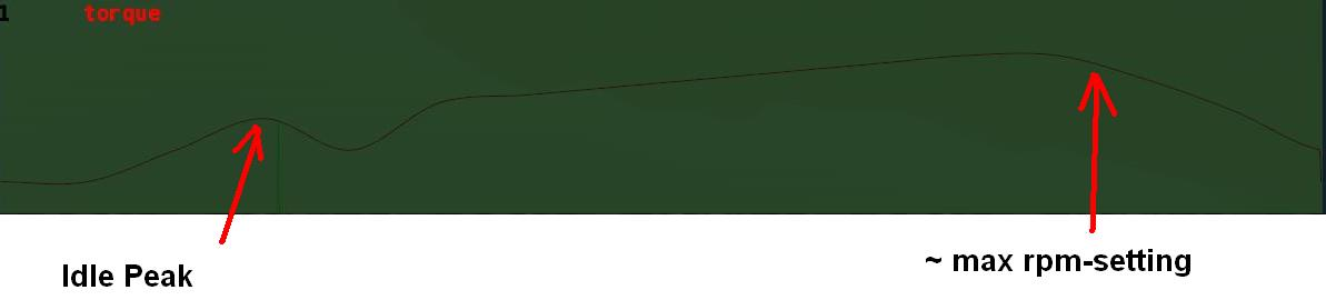 to the example above in the right spot will result the engine idle a little bit higher then
 800 rpm in first gear.
The example to the left shows a screenshot of a torquecurve made for a small diesel engine:
Idle: ~600 RPM, Max @ 1900 RPM, slight and constant torque increase over the used RPM bandwidth, hard torque drop off in the over-rev area.
Cruise Control
This section offers options to the cruise control feature (activated by pressing space bar):
- lower limit: Sets the minimum speed cruise control can be activated. Unit is meters per second (divide kph by
3.6. Example:36kph/3.6=10mps) - auto brake: If activated, the vehicle brakes if velocity is faster than set in cruise control.
0=auto brake off,1=auto brake on
;cruisecontrol lowlimit autobrake
cruisecontrol        10         1
In the example above, minimum speed for cruise control to be activated is 10mps (36kph). The auto brake feature is activated.
Speedlimiter
Limits the speed of a vehicle. If the speed is above the limit, the vehicle will not accelerate any further.
Insert the limit in meters per second (divide kph by 3.6. Example: 36 kph/3.6 =10 mps)
;speedlimiter <speed in m/s>
speedlimiter 10
In the example above, the maximum speed of the vehicle is 10mps (36kph), it will not accelerate any further.
Axles
This section defines axles on a vehicle, allowing more accurate distribution of torque among the wheels.
The axle section introduces open differentials, and spooled (aka locked) differentials. They are toggled with the W key.
By adding axles to your vehicle file you override the propulsed property for the tires. Only wheels connected to an axle are powered, if multiple axles are defined the axles are interconnected in a locked manner. If no axle section is defined the old model of equal power distribution is used.
Because the axle sections looks up already defined wheels, it must be defined AFTER the wheels have been defined.
The axle section is different from other sections in that it is broken into properties. Properties are not order dependent. Currently the available properties are:
- w1(<node1> <node2>) - This defines which wheel the axle is attached to, <node1> and <node2> Refer to the node1 and node2 as defined in the wheel section
- w2(<node1> <node2>) - Wheel 2, same as w1, this is the second wheel attached to the axle.
w1andw2are interchangeable. - d(type) - Defines the available differential types for this axle. the list of axles is cycled through in the order specified, differential types maybe specified more than once. Each differential type is specified by a single letter, the letters are not to be separated by spaces or any other character. If no differentials are specified the axles will default to opened and locked.
- Available differential types
o- Openl- Locked (wheels locked together regardless of torque input)s- Split evenly (each wheel gets equal torque regardless of wheel speed)v- Viscous [ Version 2020.01+ ] (applies locking force based on the amount of torque)
- Available differential types
Sample axle section:
axles
; axle 1
w1(1 2), w2(3 4), d(ol)
; axle 2
w1(5 6), w2(7 8), d(l)
Interaxles
In [ Version 2020.01+ ] and above you can define inter axle differentials on a vehicle, allowing more accurate distribution of torque among the axles. They are toggled with CTRL+W.
Parameters:
- axle_1: The number of the first axle, with the first defined axle starting at
1. - axle_2: The number of the second axle, with the first defined axle starting at
1. - d(type): Similar to the
axlessection
Sample interaxles section:
interaxles
; axle_1, axle_2, d(type)
2, 3, d(vlso)
Transfercase
In [ Version 2020.01+ ] and above you can add a transfer case on a vehicle.
Parameters:
- axle_1: The number of the first axle, the one which is always driven.
- axle_2: The number of the second axle, the one which is only driven in 4WD mode.
- 2wd_mode: Allows/disallows 2WD mode.
- 2wd_lo_mode: Allows/disallows 2WD Lo mode.
- gear_ratio(s): Alternate gear ratios in Lo mode. If none are specified, Lo mode will be disabled.
Notes:
- Requires an
axlessection defined first! SHIFT+Wswitches between 2WD/4WD mode.- If alternate gear ratios are specified,
ALT+Wswitches between Hi/Lo mode.
Sample transfercase section:
;Basic transfer case, no alternate ratio(s)

transfercase
;default driven axle, alternate axle, has 2wd mode, has 2wd lo mode
2, 1, 1, 0

;Transfer case with alternate ratio(s)

transfercase
;default driven axle, alternate axle, has 2wd mode, has 2wd lo mode, alternate ratio(s)
2, 1, 1, 0, 4.11, 3.1, 2.72
Wheeldetachers
[ Version 0.4.7.0+ ] this section allows you to disable power to a wheel when a detacher_group breaks.
wheeldetachers
;wheel_id, detacher_group
0, 1
1, 2
Parameters:
- wheel_id: Real number; The wheel number, with the first defined wheel starting at
0. - detacher_group: Real number; The d
etacher_groupnumber.
Example usage:
beams
;front right wheel
set_beam_defaults 12500000, 28600, 1860000, 6968000
detacher_group 1
1, 2, i
3, 4, i
5, 6, i
7, 8, i
detacher_group 0
;front left wheel
detacher_group 2
9, 10, i
11, 12, i
13, 14, i
15, 16, i
detacher_group 0

meshwheels
;tire_radius, rim_radius, width, numrays, node1, node2, snode, braked, propulsed, arm,  mass,   spring, damping, side,               meshname         material
0.35,       0.21,   0.5,      14,    1,    2,    9999,      1,         1,  18, 200.0, 300000.0,  2000.0,    l, dodgechargerwheel.mesh dodgechargerband
0.35,       0.21,   0.5,      14,    3,    4,    9999,      1,         1,  26, 200.0, 300000.0,  2000.0,    r, dodgechargerwheel.mesh dodgechargerband


wheeldetachers
;wheel_id, detacher_group
0, 1
1, 2
Collisionboxes
In [ Version 0.4.0.5+ ] you can define collisionboxes. In earlier versions of RoR, there was only one bounding box for truck activation per object, which was defined by the outermost nodes. With collisionboxes, you get the ability to define the nodes that should be used for the activation bounding box calculation. It is also possible to define multiple bounding boxes, for example to exclude some areas from activation.
Syntax:
collisionboxes
;node id list box 1
48, 58, 59, 67
;node id list box 2
5, 6
...
;node id list box n
...
Collisionboxes can give you a huge performance increase in situations where many beam objects would have been activated before, for example a container crane with many containers underneath.
Rescuer
rescuer
This single keyword placed in the truck file will make the truck a rescuer, like the Scania Wrecker. These vehicles can be entered by pressing R.
Scripts
Loads an AngelScript (*.as) file. Functions like other custom scripts except it provides an extra global variable thisActor pointing to the associated truck.
scripts
MyTruckScript.as
This feature is early in development, scripting documentation will be updated soon.
Look & Feel
Managedmaterials
Managed materials helps you to use complex material effects (for example reflective materials like chromes, dynamic damage materials) without having to deal with the technical complexity of writing a shader for Ogre3D. Rigs of Rods comes with a set of standard shader effects, and with the Managedmaterial section you can pick the effect you want and adapt it for your vehicle. The shader library will grow with time, so the set of effects available in this section will grow with time.
The generic format of this section is:
- Material name - The name of the material you are creating. You can use this material for any of your meshes (flexmeshes, props, etc.). This material name must not be defined anywhere else (for example in a .material file).
- Effect name - The name of the effect you want to use. Valid names are defined below.
- Effect parameters - A variable number of parameters, depending on the effect your are using. See below for the description.
Do not use a comma to separate parameters in a managedmaterial section! Also, you must declare your managed material before they are used. That means that the managedmaterial section should come before the flexmesh, props, wheels, or any section that will use this material.
Currently available effects:
-
flexmesh_standard - This effect defines an opaque, reflective and damageable material for flexmeshes. This will work only for flexmeshes! It takes 3 parameters:
-
A standard texture name: this is the base, undamaged texture. (The diffuse map.)
- A damaged texture name (or
-if no damage texture): Should be similar to the standard texture, but with damage. -
A specular map texture name (or
-if no specular map texture): a greyscale image that maps the "shininess" of the material, from dark for matte to white for chromed. Technically this isn't a specular map but a reflectivity map. -
flexmesh_transparent - This effect defines a semi-transparent, reflective and damageable material for flexmeshes. This will work only for flexmeshes! It takes 3 parameters:
-
A standard texture name: this is the base, undamaged texture. The alpha channel of this texture is used to define transparency. (The diffuse map.)
- A damaged texture name (or
-if no damage texture): Should be similar to the standard texture, but with damage. -
A specular map texture name (or
-if no specular map texture): A greyscale image that maps the "shininess" of the material, from dark for matte to white for chromed. Again, technically this isn't a specular map but instead a reflectivity map. -
mesh_standard - This effect defines an opaque, reflective material for any mesh (e.g. wheel rims, props, etc.) It takes 2 parameters:
-
a standard texture name: This is the base texture.
-
a specular map texture name (or
-if no specular map texture): A greyscale image that maps the "shininess" of the material, from dark for matte to white for chromed. -
mesh_transparent - This effect defines a semi-transparent, reflective material for any mesh (e.g. windows) It takes 2 parameters:
-
a standard texture name: This is the base, undamaged texture. The alpha channel of this texture is used to define transparency.
- a specular map texture name (or
-if no specular map texture): A greyscale image that maps the "shininess" of the material, from dark for matte to white for chromed.
WARNING: Your texture file names must not start with -. The parser would treat the - as "no texture placeholder" and ignore the rest.
Examples:
managedmaterials
;new_material    effect               parameters...
mainbody flexmesh_standard    mytruckbody.png mytruckbody-dmg.png mytruckbody-spec.png
windows   flexmesh_transparent mytruckbody.png mytruckbody-dmg.png mytruckbody-spec.png
wheels    mesh_standard        mytruckwheels.png mytruckwheels-spec.png
A note about shaders for power-users:
You can still use your own, non managed, Cg shaders by manually defining your .material, .program and .cg. Consult the Ogre3D documentation for more details.
If you think you have made a good shader that can be helpful to other modders, submit it to GitHub for inclusion to the managedmaterial library of RoR.
Set_managedmaterials_options
This specifies options for all FOLLOWING managed material lines.
Parameters:
- doublesided:
0(single sided) or1(double sided); default =0(single sided); . Determines if the mesh should be visible from both sides or not. IMPORTANT: This parameter treats1as "yes" and anything else as "no". This is required for backwards compatibility.
; set_managedmaterials_options doublesided
set_managedmaterials_options 1
Assetpacks
Asset packs are separately distributed zip files that can include meshes/textures/materials/etc to be used by vehicles or terrains.
Asset packs are defined in the truck file using:
assetpacks
myTruckParts.assetpack
An asset pack zip file MUST include a text file with .assetpack extension containing file info:
assetpack_name "Extra Parts for my Awesome Truck"
assetpack_description "Example asset pack"
Flares
Flares allow you to add lights to your truck. They work as light sources in OGRE and will illuminate other objects (if enabled in settings).
See also: Flares Tutorial
Required parameters:
- Reference node: Node ID; Node which defines origin of flare-placement coordinate system
- X axis node: Node ID; Node which defines X-axis of flare-placement coordinate system
- Y axis node: Node ID; Node which defines Y-axis of flare-placement coordinate system
- Flare X offset: Real number; Flare position on X axis in % of distance from ref-node to X-node
- Flare Y offset: Real number; Flare position on Y axis in % of distance from ref-node to Y-node
Optional parameters:
- Type: Character; default = f (headlight); Type of flare.
f(default mode when not stated): Low beams, toggled withNor cycled withCTRL+N.h: High beams, toggled withSHIFT+Nor cycled withCTRL+N.s: Sidelights (running/parking lights), toggled withNor cycled withCTRL+N.g: Fog lights, toggled withALT+Nor cycled withCTRL+N.b: Brake lights.t: Tail lights, activated together withfoption.l: Left blinker.r: Right blinker.R: Reverse light. (on when driving in R gear)d: Dashboard indicator. (see dashboard input source)u: User controlled light. (i.e. fog light) (see control numbers)
- Control number: Integer; default = -1 For
uflares, enter value 1-10:1would beCTRL+1,2would beCTRL+2, and so on. For other flare types, enter -1.- Special value:
12- Parking brake indicator
- Special value:
- Dashboard input source: String Enter an input source from the dashboard system. This enables flares to toggle based on dashboard UI status, such as engine ignition or locked state.
- Blink delay (ms): Integer; default = -2; Delay between on/off change, in milliseconds. A value of 500 means that the light is 500ms on and 500ms off. Use a value of 0 to create a non-blinking light.
- Special value:
-1to use the default value of 500ms. - Special value:
-2non-blinking light except blinkers, which will have default 500ms.
- Special value:
- Flare size: Real number; default = -1; This determines how big the flare will be. Reasonable values are between
0.1and5(0.1= 10% of default size). If the size is smaller then0, then the flare will be independent of the camera angle. (So the flare does not get smaller when you move the camera) - Material name: String; default = 'default'; This field determines what material should be used for the flare display. If you want to use the standard material, use
default. Please note that there is not comma between the material name and the size argument. You can usetracks/aimflareto position your flare.
Notes
[ Version 2022.12+ ] introduced the h, s, g, and t options.
Light cycling (CTRL+N) functions based on the available lights:
i. All lights off
ii. Sidelights on but only if any installed, otherwise skip to 3).
iii. Sidelights and low beams on.
iv. Sidelights, low beams and high beams on, but only if high beams are installed, otherwise cycle to 1).
Examples:
flares
;RefNode,  X,  Y, OffsetX, OffsetY, Type, ControlNumber, BlinkDelay, size MaterialName

;example for a most default one:
51,  1, 79,    0.23,    0.50,    b,            -1,          0,   -1 default

;example for a custom brake light
51,  1, 79,    0.23,    0.50,    b,            -1,        300,  0.2 myTruck/MyBrakeFlare

;example for a user controlled Fog Light (toggled by CTRL+1)
51,  1, 79,    0.23,    0.50,    u,             1,          0,  0.3 myTruck/MyFogFlare

;example for dashboard indicator
51,  1, 79,    0.23,    0.50,    d,    engine_ignition,    -1,  -1 default
Flares2
Flares2 are the same as normal flares, except that they add an offset-z argument in between:
flares2
;RefNode,  X,  Y, OffsetX, OffsetY, OffsetZ, Type, ControlNumber, BlinkDelay, size MaterialName
51,  1, 79,    0.23,    0.50,    0.50,    b,            -1,        300,  0.2 myTruck/MyBrakeFlare
Flares3
[ Version 2022.12+ ]
Flares3 functions the same as Flares2, except they take set_inertia_defaults into account. This allows for flares which can fade in/out.
flares3
set_inertia_defaults 0.4, 0.8, linear, linear
;RefNode,  X,  Y, OffsetX, OffsetY, OffsetZ, Type, ControlNumber, BlinkDelay, size MaterialName
51,  1, 79,    0.23,    0.50,    0.50,    b,            -1,        300,  0.2 myTruck/MyBrakeFlare
Materialflarebindings
See also: Flares Tutorial
This can bind a material to a flare, so that the material changes with the flare's on/off status.
The format is as follows:
- flare number: Counting starts from zero. Just count down your flares in the flares section to find the correct number.
- material name: The material that you want to change. It must contain one technique, one pass and a special Texture Unit State (see below for an example)
flares
51,1,79, 0.23, 0.50, b, -1, 300, 0.2 myTruck/MyBrakeFlare

materialflarebindings
0, myBrakeMaterial
The material must use an animated texture, as shown below:
material myBrakeMaterial
{
    technique
    {
        pass
        {
            texture_unit
            {
                anim_texture truck_brake_material.png 2 0
            }
        }
    }
}
Put the off-state of the brakelight into the file truck_brake_material_0.png and the on-state into truck_brake_material_1.png. The 2 and 0 at the end should not be changed.
This section should be after the flares section and before the props and flexbodies section in order for the lights to work properly.
COMPATIBILITY NOTE: Parameters #1 and #2 can also be separated by just space, the parser will silently accept it.
Flaregroups_no_import
Prevents a truck from importing flare states when locked or tied to another truck.
For example, this can be used to stop a truck-mounted forklift's lights from activating with the truck lights.
- Type: Character; Type of flare, e.g. low beams (
f). - Control number: Integer; default = -1 For user-controlled (
u) flares, enter value 1-10 that corresponds to the flare.
Example to prevent importing low beams and CTRL+1 user-controlled lights:
flaregroups_no_import
f
u 1
Props
This allows you to "stick" any 3D mesh to a triangle of points of a truck. You can use it to stick air intakes, horns, seats, dashboard, bumpers, whatever to the truck. Note that there will be no collision detection with these objects. Like flares, they use a vector coordinate system instead of normal right-angle coordinates. Props are positioned relative to 3 nodes of the chassis: One node is the reference node, and the two others define a base (x,y). Props are positioned relative to the reference node by adding proportions of the vectors ref->X, ref->Y, with the normal being used as well.
Parameters are:
- reference_node: Node number/name; The base node, used to define the coordinate system
- x_direction_node: Node number/name; The node that defines the X direction (this can be visualized as a line pointing from the reference node to this node)
- y_direction_node: Node number/name; The node that defines the Y direction (this can be visualized as a line pointing from the reference node to this node)
- x_offset: Real number; The amount the prop should be moved in the X direction from the reference node. The distance it is moved depends on the distance between the Reference node and the '''X direction node '''(it's proportional): (0) leaves the prop on the reference node, (1) moves it all the way to the X direction node, and (0.5) puts the prop half-way between the two
- y_offset: Real number; The amount the prop should be moved in the Y direction from the reference node. Like the X direction offset, the amount it is proportional to the distance between the reference node and the Y direction node.
- z_offset: Real number; Imagine a surface which the X and Y directions pass straight through. If looking along that surface is the forwards direction, then this field moves the prop straight up. Unlike the X direction offset and the Y direction offset, the amount for the straight up offset is measured in meters
- x_axis_rotation: Real number; The amount the prop should be rotated about the X axis
- y_axis_rotation: Real number; The amount the prop should be rotated about the Y axis
- z_axis_rotation: Real number; The amount the prop should be rotated about the 'straight up' axis
-
mesh_name_or_special_prop: String (may start with a keyword); The name of the Ogre3D mesh object used for the prop. If the mesh name starts with one of the following keywords, it will have special behavior:
-
- "dashboard": A custom dashboard + steering wheel mesh. See below.
- "dashboard-rh": A custom dashboard +steering wheel mesh on right side. See below.
- "leftmirror": Left rear view mirror.
- "rightmirror": Right rear view mirror.
- "seat": Driver's seat: Positions the driver character and turns translucent if appropriate. Skins the prop using material
driversseat. Note: if multiple "seat[2]" props are defined, the first one is the driver's seat. - "seat2": Driver's seat: Same as "seat" except it doesn't force the
driversseatmaterial. Note: if multiple "seat[2]" props are defined, the first one is the driver's seat. - "beacon": A beacon. Color and flare material are adjustable (default = orange)
- "redbeacon": A red beacon which flashes red. Fixed color and flare material.
- "lightbar": Police lightbar beacon, flashes red and blue (fixed). Also marks the vehicle as "police car" and sets up some special sounds and controls.
- "spinprop": Plane propeller.
Please note that if you want to stick wheel meshes on a wheel, the third node has to be taken from one of the outer segments.
props
;ref,  x,  y, offsetx, offsety, offsetz, rotx, roty, rotz, mesh
93, 95, 92,    0.50,    0.37,     0.0,   90,    0,    0, airintake.mesh
Note:
- The X offset and the Y offset should logically between
0and1, or if the body flexes too much the prop will not stick to the body correctly. - The coordinate system is actually really similar to 'normal coordinates', but it allows the angle between the two axes (ie. the angle between the X node, the Reference node, and the Y node) to be any value, not just
90degrees. If that angle can be made to be90degrees, then the weird coordinate system will turn into 'normal coordinates'. This can be used to make prop placement easier.
For 0.38.8 and later:
You can set the cameramode in which the prop should be shown:
    ; -2 = all the time, -1 = external only, >=0  cinecam number
    prop_camera_mode -1
You can disable shadows of the last specified flexbody:
disable_flexbody_shadows
[ Version 0.35+ ]
Disables shadow casting of the last prop to improve complex truck FPS.
disable_prop_shadow
COMPATIBILITY NOTE: Parameters #9 "Z rotation" and #10 "Mesh name" can be delimited by just space. Parser will emit a warning.
Special Prop: Dashboard
Steering wheel [ Version 0.35+ ] Here you can see the standard reference nodes, and offset for the dashboard. Then, there is the steering wheel mesh, and its offsets.
Parameters:
- reference_node: Node number/name; Like ordinary prop
- x_direction_node: Node number/name; Like ordinary prop
- y_direction_node: Node number/name; Like ordinary prop
- x_offset: Real number; Like ordinary prop
- y_offset: Real number; Like ordinary prop
- z_offset: Real number; Like ordinary prop
- x_axis_rotation: Real number; Like ordinary prop
- y_axis_rotation: Real number; Like ordinary prop
- z_axis_rotation: Real number; Like ordinary prop
- mesh_1: String with keyword "dashboard"; Mesh1: See rules below; MUST contain keyword
dashboard
- mesh_2: String; Mesh2: See rules below
- dashboard_x_offset (optional): Real number; default =
-0.67
- dashboard_y_offset (optional): Real number; default =
-0.61
- dashboard_z_offset (optional): Real number; default =
0.24
- max_turn_angle_degrees (optional): Real number; default =
160
Examples:
; NOTE: Lines starting with ; are comments

; No optional parameters: The default wheel.
; Param mesh#1 must contain "dashboard" keyword and point to a valid mesh.
; Param mesh#2 is ignored, can contain a placeholder string.
; ref,  x,  y, offsetx, offsety, offsetz, rotx, roty, rotz,                 mesh#1        mesh#2 xoffset, yoffset, zoffset, rotationangle
72, 71, 74,    0.50,     1.0,   -0.05,    0,    0,    0,      my-dashboard.mesh

; -------------------------------------------------------
; BAD EXAMPLE: Params "Mesh#2, X, Y, Z" only take effect if they are all present. The following line has the same effect like line above (Z offset is missing)!
; Param mesh#1 must contain "dashboard" keyword and point to a valid mesh.
; Param mesh#2 is ignored
; Params X, Y, Z are ignored because Z is missing.
; ref,  x,  y, offsetx, offsety, offsetz, rotx, roty, rotz,                 mesh#1        mesh#2 xoffset, yoffset, zoffset, rotationangle
72, 71, 74,    0.50,     1.0,   -0.05,    0,    0,    0,      my-dashboard.mesh           ~~~   -0.67,   -0.61,

; -------------------------------------------------------
; Params "X, Y, Z" are present: an example for a custom one with 720 degree:
; Param mesh#1 must contain "dashboard" keyword and point to a valid mesh.
; Param mesh#2 must contain a mesh name.
; ref,  x,  y, offsetx, offsety, offsetz, rotx, roty, rotz,                 mesh#1        mesh#2 xoffset, yoffset, zoffset, rotationangle
72, 71, 74,    0.50,     1.0,   -0.05,    0,    0,    0,      my-dashboard.mesh my-wheel.mesh   -0.67,   -0.51,    0.14,           720
Special Prop: Beacon
Change the beacon's color and flare material [ Version 0.35+ ]
If you want to use you own mesh as beacon it should be named beacon-<somename>.mesh, e.g. beacon-blue.mesh
The only difference between this and a standard beacon is the flarematerialname e.g. tracks/redbeaconflare which sets the color of the light, and the RGB value of the flash (The last three numbers), that sets the color of the light that is reflected from objects when the beacon lights them.
NOTE: All special parameters are required, otherwise none of them will take effect.
Parameters:
- reference_node: Node number/name; Like ordinary prop
- x_direction_node: Node number/name; Like ordinary prop
- y_direction_node: Node number/name; Like ordinary prop
- x_offset: Real number; Like ordinary prop
- y_offset: Real number; Like ordinary prop
- z_offset: Real number; Like ordinary prop
- x_axis_rotation: Real number; Like ordinary prop
- y_axis_rotation: Real number; Like ordinary prop
- z_axis_rotation: Real number; Like ordinary prop
- beacon_mesh_name: String with keyword "beacon"; The beacon mesh; MUST contain keyword
beacon
- flare_material_name: String; Material to use for the flare
- flare_color_red: Real number (
0-1); Intensity (0= full dark,1= full bright) . This color will be mixed with color of the flare texture. If the texture is white, all coloring is specified this way.
- flare_color_green: Real number (
0 - 1); Intensity (0= full dark,1= full bright). This color will be mixed with color of the flare texture. If the texture is white, all coloring is specified this way.
- flare_color_blue: Real number (
0-1); Intensity (0= full dark,1= full bright). This color will be mixed with color of the flare texture. If the texture is white, all coloring is specified this way.
Examples:
; NOTE: Lines starting with ; are comments

;ref,  x,  y, offsetx, offsety, offsetz, rotx, roty, rotz,        mesh     flareMaterialName    colorRed, colorGreen, colorBlue
; the default beacon would be:
19, 73, 16,     0.1,     0.1,       0,   90,    0,    0, beacon.mesh    tracks/beaconflare           1,        0.5,         0
; the red beacon would be:
19, 73, 16,     0.1,     0.1,       0,   90,    0,    0, beacon.mesh tracks/redbeaconflare           1,          0,         0
; example for a custom beacon:
19, 73, 16,     0.1,     0.1,       0,   90,    0,    0, beacon.mesh     tracks/greenflare           0,          1,         0
Add_animation
This directive adds an animation to last defined prop. Up to 10 rotations and offsets depending on different sources can be used on one prop.
Parameters:
- Ratio: Real number; A coefficient for the animation, prop degree if used with mode: rotation and propoffset if used with*' mode: offset*'.
- Lower limit: Real number; Empty value = 0; The lower limit for the animation, remember to use a negative value when source can be negative (as in wheel steering.) Use 0 for both options to get default limits (Full circle rotation ( -180/+180°) or -10/+10 for offsets. Limits always apply to the props' spawning position.
- Upper limit: Real number; Empty value = 0; Upper Limiter for movement, remember to use a positive value when source can be negative (as in wheel steering.). Use 0 for both options to get default limits ( Full circle rotation (-180/+180°) or -10/+10 for offsets. Limits always apply to the props' spawning position.
- (Attributes): { Key: options } pairs; Parameter consisting of name, colon, and | - delimited list of options.
source:Source type(s) joined with |; A list of sources to use, it is recommended to use only 1 per add_animation line, though multiple sources are possible too.mode:Mode type(s) joined with |; A list of modes to use, multiple modes are validevent:Key event string; An optional input, only needed for source: event. It determines the keypress event to catch for the animationlink:Dashboard source type; An optional input, only needed for source: dashboard. It determines the dashboard source to catch for the animationautoanimate(optional): "autoanimate" keyword; rotation or offset is applied as long as source is not 0. Useful for driveshafts, fans, etc.
- "noflip" (optional): "noflip" keyword; a prop will flip to the opposite limit when a limit is reached, with this mode it just stops at - "bounce" (optional): "bounce" keyword; a prop will flip to the opposite limit when a limit is reached, with this mode it just rebound at the set limit. Only useful with mode: noflip
- "eventlock" (optional): "eventlock" keyword; will lock a toggled event in its current status, useful for switches and status levers. Only works with mode:event and a correct defined event:
source:
airspeed- This prop animates with the actual speed (not speedometer indicated speed) for any vehicle.vvi- This prop animates with the vehicle's vertical velocity.altimeter100k- This prop animates with the vehicle's altitude up to 100,000 feet.altimeter10k- This prop animates with the vehicle's altitude up to 10,000 feet, at which point it will revert back to its original length.altimeter1k- This prop animates with the vehicle's altitude up to 1,000 feet, at which point it will revert back to its original length. These three animators can be used to create altimeters with three needles or similar objects/aoa- This prop animates with the dashboard's angle of attack.flap- This prop animates with the flap setting on the vehicle.airbrake- This prop animates with the airbrake setting on the vehicle.roll- This prop animates with the vehicle's roll. It will flip at180degrees roll to-180degrees roll. This option can be used for an automatic trim feature.pitch- This prop animates with the vehicle's pitch. It will flip back at180degrees pitch to-180degrees pitch. This option can be used for an automatic trim feature.throttle1- This prop animates with the throttle setting of an aircraft's first engine. This option can be used for thruster mechanics. Valid sources includethrottle1,throttle2, etc. etc. up tothrottle8.rpm1- This prop animates with the RPM of an aircraft's first engine. This option can be used for thruster mechanics. Valid sources includerpm1,rpm2, etc. etc. up torpm8.aerotorq1- This prop animates with the torque of an aircraft's first engine. Note that this only works for propeller engines, because torque is not applicable to jets. Valid sources includeaerotorq1,aerotorq2, etc. etc. up toaerotorq8.aeropit1- This prop animates with the pitch of an aircraft's first engine. Note that this only makes sense with propeller engines, pitch is not applicable to jets. Valid sources includeaeropit1,aeropit2, etc. etc. up toaerotorq8.aerostatus1- This prop animates with the On/Off/Fire status of an aircraft's first engine. Valid sources includeaerostatus1,aerostatus2, etc. etc. up toaerostatus8.brakes- This prop animates with the vehicle's brake status.accel- This prop animates with the vehicle's accelerator status.clutch- This prop animates with the vehicle's clutch status.speedo- This prop animates with the speedometer indication. It scales with the guisetting speedometer. (It is best to use it even if there is no custom overlay dashboard; it simplifies the adjustment a lot.)tacho- This prop animates with the vehicle's RPM. It scales with guisetting tachometer. (It is best use it even if there is no custom overlay dashboard; simplifies the adjustment a lot.)turbo- This prop animates with the vehicle's turbocharger PSI.parking- This prop animates with the vehicle's parking brake status.gear#- This prop animates with the specified gear. Where#is the gear number (½/3 etc).gearneutral- This prop animates with the vehicle's neutral gear.gearreverse- This prop animates with the vehicle's reverse gear.shifterman1- H-shift left/right ( Reverse | 1-2 | 3-4 | 5-6...11-12 as positions, scales with engine settings (maxGear)shifterman2- H-shift forth/back animator Reverse-2-6-8-10-12 | 1-3-5-7-9-11 as positionssequential- Sequential shift ( i.e for tiptronic or wheel shift pedals), can be used for commands too (no settable limits then)shifterlin- For auto transmission animations or gearselect indicators (special limits rules apply for this one, see below!)autoshifterlin- Same asshifterlinexcept it allows for D/N/R positions as forward gears are clamped to 1.signalstalk- For turn signal stalk animations.torque- Current engine torque.heading- This prop animates with the current heading of the truck.difflock- This prop animates with the difflock status of the truck (It only works when differentials are present in the truck.)rudderboat- This prop animates with the steering hydro on boats.throttleboat- This prop animates with the throttle status on boats.steeringwheel- This prop animates with the steering status for trucks.aileron- This prop animates with the aileron status for airplanes.elevator- This prop animates with the elevator status for airplanes.rudderair- This prop animates with the rudder status for airplanes.dashboard- This prop animates with the status of a GUI element (engine ignition, parking brake etc). Requireslink:data link argument, see below.permanent- This is a permanent source, which is always active when you are in the truck.event- A source triggered by a keypress, needs exactly one defined event.
Specials: Limits do not apply for mode:sequential. In this case the options are the F-Keynumbers of the command-movement you want to catch. Option 0, 0 with mode:sequential provides a shift_up/shift_down animation for a sequential shifter. Look into the Examples.
mode:
x-rotation- Rotate around the x-axis, in some cases special rules apply here see below (gimbal lock)y-rotation- Rotate around the y-axis, in some cases special rules apply here see below (gimbal lock)y-rotation- Rotate around the y-axis, in some cases special rules apply here see below (gimbal lock)x-offset- Offset along the x-axisy-offset- Offset along the y-axisz-offset- Offset along the z-axis
event:
- rorkeypressevent - All RoR keypress events. (A list of valid RoR events.)
link:
- dashboardsource - Any input source from the dashboard system.
How to use:
It's best to test is a prop that has no rotations or offsets set on a node triangle like this:
n1, 0, 1, 0
n2, 0, 1, 1
n3, 0, 0, 0
Add the add_animation line AFTER the prop in your prop section that you want to animate:
Sources
add_animation 200, 0, 0, source: steeringwheel, mode: x-rotation
;Prop now animated by steeringwheel input.
;Refer to the '''source:''' list above for the different sources avail.

add_animation 10, 1, 2, source: sequential, mode: y-rotation
add_animation 10, 3, 4, source: sequential, mode: x-rotation
;a joystick animation related to F1-F4 ( look below for the GIMBAL LOCK issue!)


add_animation 0.02, 1, 0, source: sequential, mode: y-offset
;button animation getting pressed on F1

add_animation 10, 0, 0, source: sequential, mode: y-offset
;sequential shifter reacting to shift up/down
Modes
add_animation 145, 0, 0, source: airspeed, mode: x-rotation
;Airspeed indicator needle rotating x axis

add_animation 145, 0, 0, source: airspeed, mode: y-rotation
;Airspeed indicator needle rotating y axis

add_animation 145, 0, 0, source: airspeed, mode: z-offset
;Airspeed indicator sliding z axis

add_animation -90, 0, 0, source: pitch , mode: y-rotation
add_animation 180, 0, 0, source: roll, mode:x-rotation
;virtual attitude indicator (artificial horizon)( look below for the GIMBAL LOCK issue!)
Events
add_animation 45, 0, 0, source: event, mode: x-rotation, event: TRUCK_TOGGLE_CONTACT
;Prop will rotate 45° x-axis when the starter key is pressed.
;There is only one event allowed with '''mode:event'''

add_animation 45, 0, 0, source:event, mode:x-rotation, eventlock, event:TRUCK_TOGGLE_CONTACT
add_animation 45, 0, 0, source:event, mode:x-rotation, event:TRUCK_STARTER
;This rotates the prop related to ignition status and additional 45° when the starter is pressed
;It is valid to stack up to 10 animations of any kind to one single prop.
Autoanimation
add_animation 0.005, 0, 0, source: permanent, mode: x-offset, autoanimate
;It will animate the related prop on the x-offset

add_animation -0.005, 0, 0, source: permanent, mode: x-offset, autoanimate
;Moving direction changed.

add_animation -0.005, 0, 0, source: permanent, mode: x-offset, autoanimate, noflip
;Will stop now at the limit and not flip anymore. So now it just moves one direction and thats it.

add_animation -0.005, 0, 0, source: permanent, mode: x-offset, autoanimate, noflip, bounce
;Will start moving left / right itself just according to the default limits

add_animation -0.005, -5, 20, source: permanent, mode: x-offset, autoanimate, noflip, bounce
;Will start moving left / right itself just according to the user custom limits.
;Keep in mind: for rotation and offset, first limits needs to be <=0  second >=0
;Limits are like prop offsets for offsets, default ( opt1=opt2=0) limit is +-10

add_animation -0.005, 15, 20, source: permanent, mode: x-offset, autoanimate, noflip, bounce
;The prop will jump instantly at start and bounce between that limits, which might be a bit confusing.

add_animation -0.005, 15, 20, source: permanent, mode: x-rotation, autoanimate
;Rotating instead of sliding. All the settings for offsets can be used with rotation too.
;Limits are in degree for rotations, default ( opt1=opt2=0) limit is +-180° ( a full circle)
GIMBAL LOCK To avoid axis corruption when rotating props: - Always place your prop with a y-rotation of 0 or 180°. If you need to align your prop in another way, rotate the mesh in your mesh-editor!
To avoid axis corruption when rotating multiple props: - Use only the x and y axis together, skip z. If you need 3 axis rotation, do the z-axis with a n/b-rotator as the base for your prop definition nodes. Gimbal lock
Flexbodies
Flexbodies are pretty much the same as props. The only difference between them is that flexbodies deform.
You can declare several flexbodies. Each must be composed of the two lines (prop-like line and forset line).
(sub-section) "Prop-like"
The first line of this section is exactly the same format as on the props section. Parameters:
- reference_node: Node number/name; The base node, used to define the coordinate system.
- x_direction_node: Node number/name; The node that defines the X direction (this can be visualized as a line pointing from the reference node to this node)
- y_direction_node: Node number/name; The node that defines the Y direction (this can be visualized as a line pointing from the reference node to this node)
- x_offset: Real number <0 - 1>; The amount the prop should be moved in the X direction from the reference_node.
- y_offset: Real number <0 - 1>; The amount the prop should be moved in the Y direction from the reference_node.
- z_offset_meters: Real number; Moves the flexbody "straight up". Unlike the x_offset and the y_offset, the distance is measured in meters.
- x_axis_rotation: Real number; The amount the flexbody should be rotated about the X axis
- y_axis_rotation: Real number; The amount the flexbody should be rotated about the Y axis
- z_axis_rotation: Real number; The amount the flexbody should be rotated about the 'straight up' axis
- mesh_name: String; The name of the Ogre3D mesh object used for the flexbody.
(sub-directive) forset
As next, a line beginning with the word forset follows. Behind the word forset, you declare all nodes used for the deformation of the mesh (ranges are supported).
- node_list: List of node{number/name/range}; List of nodes to use for deforming the flexbody. These nodes should be outer nodes of the vehicle, those that are close to the mesh.
(sub-directive) forvert
An additional line added after forset enabling manual override of node bindings for specified vertices. The specified nodes do not need to be in forset node list. Processing works the same as forset: the game calculates the offset between the nodes and the vertex and maintains it.
- reference_node: Node number/name; The base node, used to define the coordinate system
- x_direction_node: Node number/name; The node that defines the X direction (this can be visualized as a line pointing from the reference node to this node)
- y_direction_node: Node number/name; The node that defines the Y direction (this can be visualized as a line pointing from the reference node to this node)
- vertex_list: List of vertices; List of mesh vertices to use for deforming the flexbody, ranges are supported. Vertex numbers can be viewed in-game using the "Flexbody debug" tool from Top Menubar -> Tools.
Note
The verts: intermediate line before the vertex list is required!
forvert 25, 0, 2, verts: 70-71, 28
Notes about backwards compatibility:
- If you use a node range [A-B], RoR will tolerate if node B doesn't exist (warning will be emitted).
- If you enter multiple commas
,,between forset entries, parser will ignore it silently. - If there's a comma after last element, parser will ignore it silently.
- Accepted separators between keyword "forset" and node ranges are: whitespace, comma
,, colon:, or nothing at all (lines likeforset12,34,56will be correctly evaluated asforset 12, 34, 56) for backwards compatibility.
(sub-directive) disable_flexbody_shadow
(optional) [ Version 0.38.8+ ]
No parameters. Disables shadow casting of the last flexbody to improve complex truck FPS.
(sub-directive) flexbody_camera_mode
(optional) [ Version 0.38.8+ ]
Sets the cameramode in which the flexbody should be shown:
- mode: Decimal number default =
-2(always visible); Flexbody visibility:-2= all the time (default),-1= external only, >=0cinecam number
flexbodies
;ref,  x,  y, offsetx, offsety, offsetz, rotx, roty, rotz, mesh
3,  4, 19,       0,       0,   0.027,   90,    0,   90, dodgecharger.mesh
forset 0-16, 23-24, 31, 54-125

disable_flexbody_shadow

; -2 = all the time, -1 = external only, >=0  cinecam number
flexbody_camera_mode -1
Note: It's important to keep an eye on the number of vertices of your meshes. Not that there is a hard limit, but beyond 10000 vertices there could be a noticeable slowdown. As reference: the Dodge Charger mesh is about 4000 vertices.
Submesh
Defines the collision surface of the truck; see required subsection cab and option c
It may also generate textured mesh to visualize the truck; see optional subsection texcoords
(sub-section) cab
Specifies a series of triangles. Order of nodes defines orientation - the side with counterclockwise winding will be 'front' (or 'positive'), the other 'rear' (or 'negative'). If texcoords are used, only the 'front' side will be visible, the 'rear' side will be see-through (or black if you use backmesh).
- node_1: Node number; First point of collision triangle.
- node_2: Node number; Second point of collision triangle.
- node_2: Node number; Third point of collision triangle.
- options (optional): String
n: Placeholder. Does nothing.c: This triangle will be a contact triangle that can contact with contacters nodes. Deprecated aliases:p,u.b: This triangle will be part of a buoyant hull. Deprecated aliases:D,F,S.s: This triangle will be part of a buoyant hull, mouse dragging will be disabled.r: This triangle will be part of a buoyant hull, mouse dragging only.
(sub-section) texcoords
Specifies texture coordinates (also called 'UV coordinates') for cab triangles. Only triangles with all 3 texcoords are displayed. The texture is specified in globals section.
- node: Node number; Node representing a vertex in the resulting geometry.
- u: Real number 0.0 - 1.0; The U texture coordinate: Position of this vertex on the X axis of the image.
- v: Real number 0.0 - 1.0; The V texture coordinate: Position of this vertex on the Y axis of the image.
(sub-directive) backmesh
No params. If added, the triangles' backsides (see texcoords) will be black instead of see-through.
;cabin top
submesh
texcoords
75, 0.172, 0.334
76, 0.172, 0.665
77, 0.291, 0.334
78, 0.291, 0.665
cab
75,76,78
75,78,77

;cabin back
submesh
texcoords
77, 0.291, 0.334
78, 0.291, 0.665
53, 0.422, 0.334
54, 0.422, 0.665
6, 0.422, 0.334
8, 0.422, 0.665
cab
77,78,54
77,54,53
53,54,8,c
53,8,6,c
backmesh
Example of invisible collision submesh for a flexbody vehicle (texcoords section is not used):
;front bumper
submesh
cab
126,121,127,c
132,126,127,c
133,132,127,c
125,120,121,c
126,125,121,c
...
set_collision_range
set_collision_range is 0.02 as default value, and defines the maximum range (2 cm) around a truck's collision triangles that collisions start to happen.
By increasing it, for example to 0.04, penetrations become a lot more difficult.
set_collision_range 0.02
submesh_groundmodel
Specifies groundmodel should be used for the trucks contactive submeshes. It has module-wide effect; it only needs to be defined once per file.
Parameter:
- groundmodel_name: String; default = concrete; The groundmodel to use. See also Groundmodel Description File
;submesh_groundmodel groundModelName
submesh_groundmodel rock
Exhausts
This replaces the x or y node options. The factor parameter should be "1", because it is not used yet. The material should be "default" if no user-created one is made. (You could create your own particle emitter based on the default one: data/smoke.particle). Remember: The direction node is behind the ref node!
exhausts
;ref node, direction node, factor material
103,             99,      1 default
105,             98,      1 default
Sections
This section allows you to have different options selectable from the vehicle spawner menu. Almost any section (managedmaterials, engine, props, flexbodies, etc) can be used with this.
sectionconfig 0 lowspeed
sectionconfig 0 highspeed

section 0 lowspeed
engine
1000.000000, 1500.000000, 5000.000000, 2.000000, 10.850000, 9.520000, 6.560000, -1.000000
end_section
section 0 highspeed
engine
1000.000000, 15000.000000, 5000.000000, 2.000000, 10.850000, 9.520000, 6.560000, -1.000000
end_section
Guisettings
By using this section you can set some parameters of the Truck GUI. This can be helpful if you're building a vehicle that has a relatively higher or lower speed than average.
Format: keyword
- dashboard: [ Version 0.38.66+ ] Custom HUD layout that should be used for this truck. You can use multiple lines.
- texturedashboard: [ Version 0.38.66+ ] Custom HUD layout that should be used for the RTT for this truck. You can use multiple lines. RTT means Real Time-generated Texture, you can use it as material for your custom dashboard mesh.
- interactiveOverviewMap: [ Version 0.36+ ]; off / simple / zoom - Enables/disables the activation of the interactive map for the truck.
- shifterAnimTime: Sets how much a shifter prop animation should be smoothed. Default
0.4, use0.0to disable.
Legacy parameters (not affecting the v0.4 custom HUD system). Will be restored or removed soon.
- tachoMaterial: String; default = tracks/Tacho; The name of the tachometer face material. (must be defined in a material file).
- speedoMaterial: String; default = tracks/Speedo; The name of the speedometer face material. (must be defined in a material file).
- speedoMax: Positive decimal number; default = 140; The highest number that is on the speedometer (kph). (values 10-32000) Speedometer needle goes from -140° to 140°.
- useMaxRPM: 0 or 1; default = 0; [Yes/No] Whether or not to use the max rpm (in the engine section) as the highest number on the tachometer. Note that your actual max rpm is MaxRPM+20%. Do not include the 20% on your tachometer or it will be inaccurate. Tachometer needle is from -120° to 120°.
- helpMaterial: String; default = tracks/black; The help material (a picture that shows command instructions). NOTE: This value overrides settings from section "help"
Since version 2026.01, each texturedashboard is rendered to a different RTT texture. The first texturedashboard is rendered to RTTTexture1, the second one to RTTTexture2, and so on. There are 10 textures available and you can preview them using the Texture Tool in Tools > Texture tool.
Example:
guisettings
interactiveOverviewMap zoom
dashboard dash_test.layout
dashboard dash_test2.layout
; Will be rendered to RTTTexture1
texturedashboard dashGauges.layout
; Will be rendered to RTTTexture2 (since 2026.01)
texturedashboard advancedDash.dashboard
; legacy settings
tachoMaterial tracks/MyTacho
speedoMaterial tracks/MySpeedo
speedoMax 80
useMaxRPM 1
Customdashboardinputs
[ Version 2026.01+ ]
Adds custom input sources to the vehicle's dashboard system. These inputs can be modified using scripts, allowing you to implement highly-customized and complex behaviours.
Parameters:
- input_name: Custom input name. Do not use built-in names! It's highly recommended to use names that are unique enough to avoid conflicts, since dashboard mods can also add custom inputs! An unique name could be something like
VehicleName_CustomInput_InputName. - data_type: Input data type. Allowed types:
bool,int,float,string. The correct data type for the input depends on its purpose. For instance, you usefloatto rotate images or animate props,intto control series,boolto control lamps or flares, andstringto add text to your dashboard.
Example:
customdashboardinputs
VehicleName_CustomInput_DieselGlowPlugLight bool
VehicleName_CustomInput_FuelLevel float
VehicleName_CustomInput_GaugeFaceType int
VehicleName_CustomInput_ClockString string
Set_skeleton_settings
Inline-section; modifies the skeleton display (activated by pressing K) of the truck. Has module-wide effect; only needs to be issued once per file.
Parameters:
-
visibility_range_in_meters (nullable): Real number; default = 150; Empty value = -1
-
beam_thickness_in_meters (optional) (nullable): Real number; default = 0.01 (1 centimeter); Empty value = -1
Examples:
Beams visible from 150 meters away, beams are 1 centimeter in width (default values):
set_skeleton_settings 150, 0.01
2km sight range with 9 centimeter wide beams:
set_skeleton_settings 2000, 0.09
Videocamera
The videocamera section describes how to set up multiple mirrors and extra cameras like a backup-camera for a truck or hook-camera for a crane.
Both, cameras and mirrors, use the same technique, cameras just add a reflective calculation and flip (mirror) the image generated.
Parameters:
- reference_node: Node number/name; The node where the camera is placed. This is your reference node. Any existing node## is valid.
- left_node: Node number/name; The Z-reference of the camera, should be exactly right of the reference node when the camera points forward to the trucks front. Any existing node## is valid.
- bottom_node: Node number/name; The Y-reference of the camera, should be exactly below the reference node when the camera points forward to the trucks front. Any existing node## is valid.
- alt_reference_node (nullable): Node number/name; Empty value = -1; The alternative cam position node. It replaces the reference node for position but not for orientation. Good to setup mirrors and cams with just one extra node to an existing truck. Important for mirrors, read below! Any existing node## is valid.
- alt_orientation_node (nullable): Node number/name; Empty value = -1; The alternative camera orientation node. If set, it skips any camera orientation calculation and makes the cam permanent look at the set node. Good for hooks moving up and down. Any existing node## is valid.
- offset_x (nullable): Real number; Empty value = 0; X-offset from reference or alternative cam position node. Works like props offsets, relates to the plane of Node 1-3 as frustum and moves the cam proportional forth and back on its roll-axis.
- offset_y (nullable): Real number; Empty value = 0; Y-offset from reference or alternative cam position node. Works like props offsets, relates to the plane of Node 1-3 as frustum and moves the cam up and down in meters on its rotation-axis.
- offset_z (nullable): Real number; Empty value = 0; Z-offset from reference or alternative cam position node. Works like props offsets, relates to the plane of Node 1-3 as frustum and moves the cam proportional left and right on its pitch-axis.
- rotation_x (nullable): Real number; Empty value = 0; Optional camera X-rotation. Works like props rotation, relates to the plane of Node 1-3 as frustum. Adjust camera orientation without moving nodes.
- rotation_y (nullable): Real number; Empty value = 0; Optional camera Y-rotation. Works like props rotation, relates to the plane of Node 1-3 as frustum. Adjust camera orientation without moving nodes. Avoid the gimbal lock, using Y-rotation is not recommended together with other axis.
- rotation_z (nullable): Real number; Empty value = 0; Optional camera Z-rotation. Works like props rotation, relates to the plane of Node 1-3 as frustum. Adjust camera orientation without moving nodes.
- fov: Real number, valid: 0.01 -179.9; Camera field of view.
- texture_width: Positive decimal, must be power of 2; X-resolution of the texture generated. Valid: any value^2 (POW) (see below for explanation), recommended maximum
256, watch your FPS. - texture_height: Positive decimal, must be power of 2; Y-resolution of the texture generated. Valid: any value^2 (POW) (see below for explanation), recommended maximum
256, watch your FPS. - min_clip_distance: Real number; Minimum distance in meters of objects to be rendered Valid:
0.1- value<maxclipdistance. Useful to blend out things that should not be displayed. Good to tune FPS. - max_clip_distance: Real number Maximum distance in meters of objects to be rendered Valid: value>minclipdistance -
32000. Useful to blend out things that should not be displayed. Watch your FPS. - camera_role: Decimal number; Role aka function of the camera:
-1== Camera
0== Tracker camera (requires an alternative camera orientation node)
1== Mirrors
2== Same as mirrors (1) but without flipping the texture horizontally (expects texcoords to be already flipped in the mesh). - camera_mode: Decimal number, use -2; Camera switchoff state. Not supported yet, put a
-2in here. - material: String; The material the generated textured should be displayed on. Requires a prop (mesh) using this material to get any visual results.
- name: [ Version 0.38.63+ ] String; Specify a name for this videocamera that might be used for the title of the renderwindow.
Important:
- Videocameras only work with props.
- Place the videocamera section before loading any meshes that should display the material
- Its recommended that mirrors always use the alternative cam position node placed precise in the center of the mirror-mesh (the reflecting part) of the related mirror. Otherwise, reflective calculation might be wrong. Mirrors can use y-axis rotation presets for easy adjustment, to rotate x/z axis move the reference nodes accordingly to avoid gimbal lock, offset preset work too, but are not recommended to use.
- Wrong or not existing materials might make RoR crash while parsing the truck. Be accurate !
.materialfile material definition is strictly necessary and needs to match the material in the truck-file line. Material definition features a fall-back texture when camera is not active or not set. Just add a texture unit with a texture definition, it will be replaced with the generated texture when camera is setup correct and active automatically.- Do NOT the set alternative camera orientation node to the same node## then your reference node or ( if used ) the alternative cam position node. Makes no sense and might crash.
Samples:
videocamera
;nref, nx, ny, ncam, nlookat,    offx,  offy,  offz, rotx, roty, rotz, fov, texX, texY, minclip, maxclip, cRole, cMode, material
; camera with no offsets and rotations
43, 42,  1,   -1,      -1,    0.00,  0.00,  0.00,    0,    0,    0,  70,  256,  256,    0.10,    2500,    -1,    -2, video-camera1

; camera with no offsets and rotations placed on an alternative camNode
43, 42,  1,  185,      -1,    0.00,  0.00,  0.00,    0,    0,    0,  70,  256,  256,    0.10,    2500,    -1,    -2, video-camera1

; tracker camera with no offsets and rotations placed on an alternative camNode
43, 42,  1,  185,     363,    0.00,  0.00,  0.00,    0,    0,    0,  70,  256,  256,    0.10,    2500,     0,    -2, video-camera1

; camera  with offsets and rotations
42, 43,  1,  362,      -1,   -3.22,  1.20,  0.00,  -45,    0,    0, 100,  128,  128,    0.01,    2500,    -1,    -2, video-camera1

; camera  with offsets and rotations placed on an alternative camNode (offsets apply from here)
42, 43,  1,  362,      -1,   -3.22,  1.20,  0.00,  -45,    0,    0, 100,  128,  128,    0.01,    2500,    -1,    -2, video-camera1

; mirror no offsets and rotations placed on an alternative camNode
43, 42,  1,  185,      -1,    0.00,  0.00,  0.00,    0,    0,    0,  70,  256,  256,    0.10,    2500,     1,    -2, video-camera1
Example mirror setup from the 1988 Audi UR-Quattro:
videocamera
;nref, nx, ny, ncam, nlookat,    offx,  offy,  offz, rotx, roty, rotz, fov, texX, texY, minclip, maxclip, cRole, cMode, material
;left
317,308,315,  318,     -1,   0,   2,   0,   0,   10,   0,  40,  400,  400,     0.1,    6000,     1,    -2, Quattro_LM
UV Mapped mirror mesh:
You can use this texture to help UV map your mirror mesh:
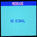
.material file:
material Quattro_LM
 {
    technique
    {
       pass
        {
          texture_unit
          {
            texture vidscreen-disabled.png
          }
       }
    }
}
Node position reference:
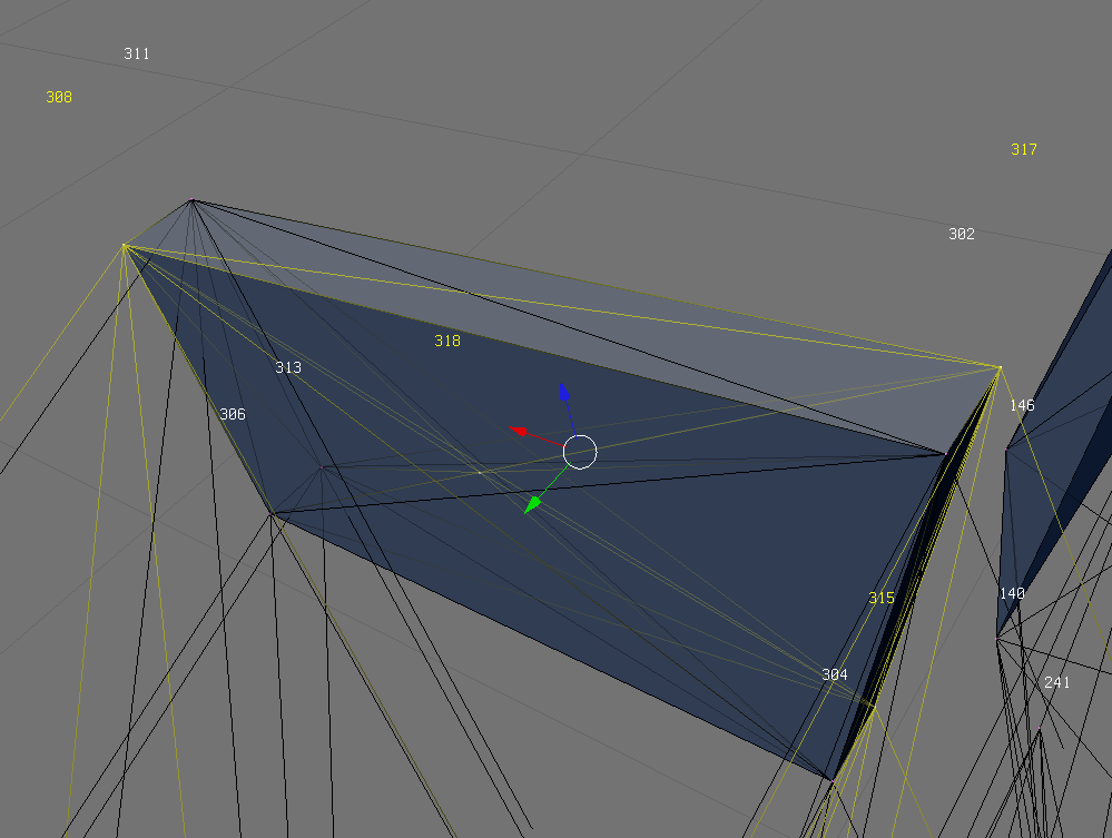
Make sure vidscreen-disabled.png is in your truck zip. Use your own texture and material names to avoid conflicts!
You can enable videocamera debug in settings (Diagnostic tab) which activates helpful meshes which show position and orientation of the video-cameras set up:
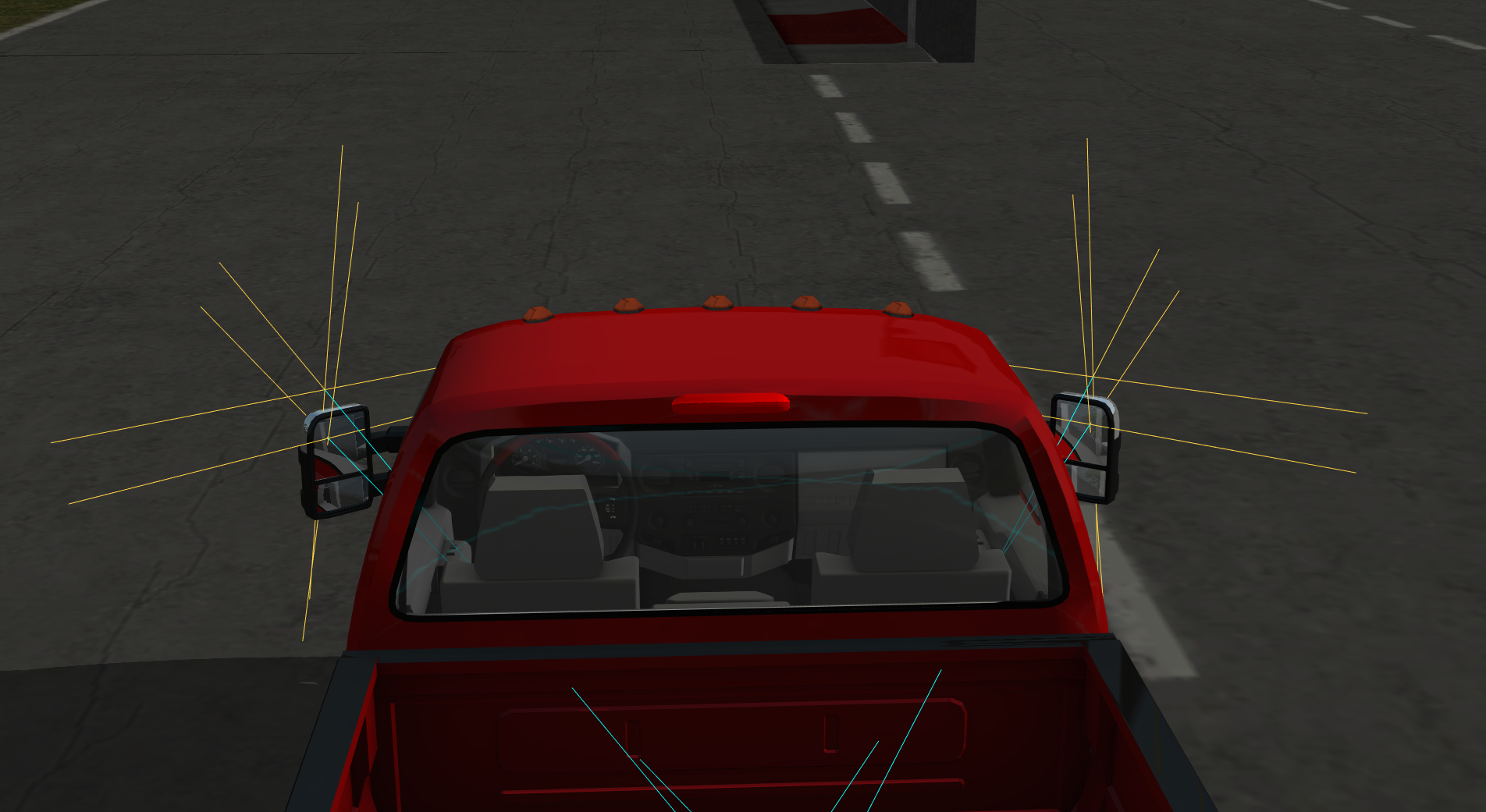
Notes:
- Any value
2^n(POW) means that you have to choose a number out of the following numbers:
    2^0 = 1
    2^1 = 2
    2^2 = 4
    2^3 = 8
    2^4 = 16
    2^5 = 32
    2^6 = 64
    2^7 = 128
    2^8 = 256
    2^9 = 512
    2^10 = 1024
    2^11 = 2048
    2^12 = 4096
    2^13 = 8192
Extcamera
The extcamera command allows you to change the 3rd person camera behavior.
Currently, there are three modes you can use:
The classic mode (also default if you do not use this command)
extcamera classic
The cinecam mode: it will rotate the camera around the cinecamera
extcamera cinecam
The node mode: it will rotate the camera around a specified node
;extcamera node <nodeid>
;for example:
extcamera node 123
The final two modes are useful for a vehicle with detaching parts, so the camera is fixed in the view of the main vehicle.
Note
You can manually set the extcamera by middle-clicking a node. Reset by middle-clicking an area away from the vehicle.
Camerarail
In [ Version 0.39.7+ ] and above you can add a camerarail section to your beam objects. The camerarail generates a cSpline on base of the given nodes, on which you can move a camera. A new camera mode will be added ingame which is accessible with the "c"-button.
Camera controls:
- Right-click: Rotate camera
- Right-click +
CTRL(left) + move mouse left/right: Move camera on spline. Speed up withShiftor slow down withAlt. CTRL(left) +Shift+Space: Enable/disable auto-tracking
Syntax:
camerarail
<node1>
[node2]
...
[node50]
You can define up to 50 nodes per beam object. You can use one node several times. If the first node is the same as the last one, the spline will be closed and the camera can move on the rail continuously. Example:
camerarail
5
6
7
8
5
If multiple beam objects, each with a camerarail section, are connected with hooks, the game will try to connect the splines.
This way you can move the camera over multiple hooked vehicles without the need to switch the vehicle:
Object A (active) - Object B (hooked) - Object C (hooked)
The distance between the last camerarail node of one and the first camerarail node of another object needs to be under 5 meters.
Sounds
Since [ Version 0.36+ ], vehicles can have custom sounds. By default, RoR uses a set of default sounds for your vehicle, but with the following sections you can customize these sounds.
disabledefaultsounds
Use this simple statement to disable all sounds that RoR automatically adds to your vehicle. This allows you to start from a clean slate, and add your custom sounds without interference from the automatically added sounds. Example:
disabledefaultsounds
Soundsources
Adds a sound source to your vehicle.
Parameters:
- node: Node number; The place where your sound will come from. Doesn't support named nodes.
- sound_script_name: String; Sound scripts are defined in soundscript files. You can use game-defined sound scripts or your own sound scripts.
soundsources
;nodeID, sound
23, my_diesel
23, my_turbo
135, tracks/default_horn
Soundsources2
Parameters:
- node: Node number; The place where your sound will come from. Doesn't support named nodes.
- mode: Decimal number
- -2: Global; enabled all the time
- -1: Enabled in external camera only
- 0 (or higher): Enabled for cinecamera number specified. Note: for backwards compatibility, the parser will read invalid values as
0and emit a warning.
- sound_script_name: String; Sound scripts are defined in soundscript files. You can use game-defined sound scripts or your own sound scripts.
soundsources2
;node, mode, sound
23,   -2, my_diesel
23,   -1, my_turbo
135,    0, tracks/default_horn
List of default soundsources
This is a list of all default soundsources separated by engine type
This can be inserted in the file as is.
Engine (Diesel)
soundsources
1, tracks/default_diesel
1, tracks/default_force
1, tracks/default_starter
1, tracks/default_turbo
1, tracks/default_air_purge
1, tracks/default_horn
1, tracks/default_pump
1, tracks/default_screetch
1, tracks/default_brakes
1, tracks/default_parkbrakes
1, tracks/default_air
1, tracks/default_shift
1, tracks/default_break
1, tracks/default_creak
1, tracks/default_gear_slide
1, tracks/default_reverse_beep
1, tracks/default_turn_signal
Engine (Gasoline)
soundsources
1, tracks/default_car
1, tracks/default_starter
1, tracks/default_horn
1, tracks/default_pump
1, tracks/default_police
1, tracks/default_screetch
1, tracks/default_brakes
1, tracks/default_parkbrakes
1, tracks/default_shift
1, tracks/default_break
1, tracks/default_creak
1, tracks/default_gear_slide
1, tracks/default_turn_signal
Airplane (Prop)
soundsources
1, tracks/default_turboprop_start1
1, tracks/default_turboprop_lopower1
1, tracks/default_turboprop_hipower1
1, tracks/default_turboprop_start2
1, tracks/default_turboprop_lopower2
1, tracks/default_turboprop_hipower2
1, tracks/default_turboprop_start3
1, tracks/default_turboprop_lopower3
1, tracks/default_turboprop_hipower3
1, tracks/default_turboprop_start4
1, tracks/default_turboprop_lopower4
1, tracks/default_turboprop_hipower4
1, tracks/default_turboprop_start5
1, tracks/default_turboprop_lopower5
1, tracks/default_turboprop_hipower5
1, tracks/default_turboprop_start6
1, tracks/default_turboprop_lopower6
1, tracks/default_turboprop_hipower6
1, tracks/default_turboprop_start7
1, tracks/default_turboprop_lopower7
1, tracks/default_turboprop_hipower7
1, tracks/default_turboprop_start8
1, tracks/default_turboprop_lopower8
1, tracks/default_turboprop_hipower8
Airplane (Jet)
soundsources
1, tracks/default_turbojet_start1
1, tracks/default_turbojet_lopower1
1, tracks/default_turbojet_hipower1
1, tracks/default_turbojet_afterburner1
1, tracks/default_turbojet_start2
1, tracks/default_turbojet_lopower2
1, tracks/default_turbojet_hipower2
1, tracks/default_turbojet_afterburner2
1, tracks/default_turbojet_start3
1, tracks/default_turbojet_lopower3
1, tracks/default_turbojet_hipower3
1, tracks/default_turbojet_afterburner3
1, tracks/default_turbojet_start4
1, tracks/default_turbojet_lopower4
1, tracks/default_turbojet_hipower4
1, tracks/default_turbojet_afterburner4
1, tracks/default_turbojet_start5
1, tracks/default_turbojet_lopower5
1, tracks/default_turbojet_hipower5
1, tracks/default_turbojet_afterburner5
1, tracks/default_turbojet_start6
1, tracks/default_turbojet_lopower6
1, tracks/default_turbojet_hipower6
1, tracks/default_turbojet_afterburner6
1, tracks/default_turbojet_start7
1, tracks/default_turbojet_lopower7
1, tracks/default_turbojet_hipower7
1, tracks/default_turbojet_afterburner7
1, tracks/default_turbojet_start8
1, tracks/default_turbojet_lopower8
1, tracks/default_turbojet_hipower8
1, tracks/default_turbojet_afterburner8
Airplane (Piston)
soundsources
1, tracks/default_pistonprop_start1
1, tracks/default_pistonprop_lopower1
1, tracks/default_pistonprop_hipower1
1, tracks/default_pistonprop_start2
1, tracks/default_pistonprop_lopower2
1, tracks/default_pistonprop_hipower2
1, tracks/default_pistonprop_start3
1, tracks/default_pistonprop_lopower3
1, tracks/default_pistonprop_hipower3
1, tracks/default_pistonprop_start4
1, tracks/default_pistonprop_lopower4
1, tracks/default_pistonprop_hipower4
1, tracks/default_pistonprop_lopower5
1, tracks/default_pistonprop_hipower5
1, tracks/default_pistonprop_lopower6
1, tracks/default_pistonprop_hipower6
1, tracks/default_pistonprop_lopower7
1, tracks/default_pistonprop_hipower7
1, tracks/default_pistonprop_lopower8
1, tracks/default_pistonprop_hipower8
Marine (Large)
1, tracks/default_marine_large
Marine (Small)
1, tracks/default_marine_small
Aircraft
Wings
Please see this page for more information
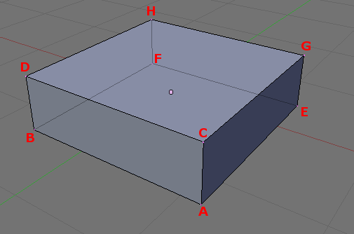
The wings parameters are:
- A Front left down node number
- B Front right down node number
- C Front left up node number
- D Front right up node number
- E Back left down node number
- F Back right down node number
- G Back left up node number
- H Back right up node number
- Texture X coordinate of the front left of the wing: in the texture defined in "globals"
- Texture Y coordinate of the front left of the wing: in the texture defined in "globals"
- Texture X coordinate of the front right of the wing: in the texture defined in "globals"
- Texture Y coordinate of the front right of the wing: in the texture defined in "globals"
- Texture X coordinate of the back left of the wing: in the texture defined in "globals"
- Texture Y coordinate of the back left of the wing: in the texture defined in "globals"
- Texture X coordinate of the back right of the wing: in the texture defined in "globals"
- Texture Y coordinate of the back right of the wing: in the texture defined in "globals"
- Type of control surface: see below
- Relative chord point at which starts the control surface (between 0.0 and 1.0)
- Minimum deflection of the control surface: in degrees (negative deflection)
- Maximum deflection of the control surface: in degree (positive deflection)
- Airfoil file to use
- coefficent (optional) Default is
1.0(100%), setting any other positive number increases or decrease overall wing efficacy. Useful for precision flight characteristics tuning.
The type of control surface is set by a single character, and defines how the control surface will move depending on pilot inputs. Available control surface types are:
n= Nonea= Right aileronb= Left aileronf= Flape= Elevatorr= RudderS= Stabilator with right hand axis (full body elevator), useful for e.g. a Mig25-
T= Stabilator with left hand axis (full body elevator), useful for e.g. a Mig25 -
c= Right elevon (right aileron + elevator), useful for e.g. Concorde d= Left elevon (left aileron + elevator), useful for e.g. Concordeg= Right flaperon (right aileron + flap)h= Left flaperon (left aileron + flap)U= Taileron with right hand axis (full body elevator+aileron), useful for e.g. a F-15V= Taileron with left hand axis (full body elevator+aileron), useful for e.g. a F-15i= Right ruddervator (rudder + elevator), useful for V-tails like the Bonanzaj= Left ruddervator (rudder + elevator), useful for V-tails like the Bonanza
wings
;main wing
28,22,29,23,18,20,19,21, 0.509, 0.999, 0.555, 0.751, 0.752, 0.999, 0.752, 0.751, a, 0.75, -24, 24, NACA64.1.412.afl
; this wing is force efficacy reduced to 50%
26,28,27,29,16,18,17,19, 0.804, 0.711, 0.818, 0.617, 0.999, 0.711, 0.999, 0.617, f, 0.75, -30, 0, NACA64.1.412.afl 0.75
; this wing is force efficacy upgraded to 300% ( equals 3 wings of the same type )
90,26,25,27,14,16,15,17, 0.783, 0.844, 0.804, 0.711, 0.999, 0.844, 0.999, 0.711, f, 0.75, -30, 0, NACA64.3.618.afl 3.0
 0,90,24,25, 4,14,13,15, 0.764, 0.933, 0.784, 0.844, 0.999, 0.933, 0.999, 0.844, f, 0.75, -30, 0, NACA64.3.618.afl
 2, 0,46,24, 6, 4,12,13, 0.756, 0.999, 0.764, 0.933, 0.999, 0.999, 0.999, 0.933, n, 1.0, 0, 0, NACA0009.afl
44, 2,45,46,30, 6,31,12, 0.783, 0.844, 0.764, 0.933, 0.999, 0.844, 0.999, 0.933, f, 0.75, -30, 0, NACA64.3.618.afl
42,44,43,45,32,30,33,31, 0.804, 0.711, 0.783, 0.844, 0.999, 0.711, 0.999, 0.844, f, 0.75, -30, 0, NACA64.3.618.afl
40,42,41,43,34,32,35,33, 0.818, 0.617, 0.804, 0.711, 0.999, 0.617, 0.999, 0.711, f, 0.75, -30, 0, NACA64.1.412.afl
38,40,39,41,36,34,37,35, 0.555, 0.751, 0.509, 0.999, 0.752, 0.751, 0.752, 0.999, b, 0.75, -24, 24, NACA64.1.412.afl
;rudder
101,107,102,108,103,109,104,110, 0.017, 0.746, 0.087, 0.492, 0.262, 0.746, 0.204, 0.492, r, 0.56, -35, 35, NACA0009.afl
99,101,100,102,105,103,106,104, 0.017, 0.999, 0.132, 0.747, 0.262, 0.999, 0.253, 0.747, n, 1.0, 0, 0, NACA0009.afl
;elevators
144,154,146,155,142,152,105,153, 0.763, 0.457, 0.840, 0.244, 0.999, 0.457, 0.983, 0.244, e, 0.64, -33, 33, NACA0009.afl
145,144,147,146,143,142,106,105, 0.756, 0.999, 0.764, 0.933, 0.999, 0.999, 0.999, 0.933, n, 1.0, 0, 0, NACA0009.afl
150,145,151,147,148,143,149,106, 0.840, 0.244, 0.763, 0.457, 0.983, 0.244, 0.999, 0.457, e, 0.64, -33, 33, NACA0009.afl
Special wing formats to reduce node/beam count and CPU load:
(Use at own risk!)
All examples lines refer to the node notation sample picture above.
'A' means Node A from that schematic diagram.
They work, no idea if they produce more or less lift then a wing with defined thickness.
Only use them for invisible wings with meshed props/flexbodies for the visual appearance and with a transparent material, skinning them results in an ugly visual appearance.
- Flarewing using 2 nodes
For precise aviation flare placement you can use a wing defined with only 2 nodes. It has no aerodynamic influence at all It has an extremely low node/beam count -- Vital: Needs to be placed as first wing in the wings section. Use NACA0009.afl as the airfoil.
wings
A,B,A,B,A,B,A,B,0,0,0,0,0,0,0,0,n,0,0,0, NACA0009.afl
- Trim or main wing using 3 nodes
-- Defines a wing using only 3 nodes. Placing this wing first in the wing section results in the aviation flares appearing on the nodes A,B ( red/green ) and E (white flash).
Works horizontally and vertically. (As on the tail.) Low node/beam count wing for self built flaps, ailerons, elevators or trimwings, very easy to animate with a single hydro.
Can be used with any active control surface and any afl-format
Known Issues: Sometimes vertical tailfin wings work only one direction. If RoR crashes exchange node A and B with each other.
wings
A,B,A,B,E,E,E,E,0,0,0,0,0,0,0,0,n,0,0,0, NACA0009.afl
- Trim or main wing using 4 nodes
-- Defines a wing using only 4 nodes. Placed first in the wing section results in the aviation flares appearing on the nodes A,B (red/green) and E,F (white flash)
Works horizontally and vertically (As on the tail.)
Low node/beam count wing for main wings
Can be used with any active control surface and any afl-format.
Known Issues: sometimes vertical tailfin wings work only one direction. If RoR crashes exchange node A,B and E,F with each other
wings
A,B,A,B,E,F,E,F,0,0,0,0,0,0,0,0,n,0,0,0, NACA0009.afl
Airbrakes
Airbrakes are a moving panel used to slow down an airplane (key bindings: 3 and 4). They are positioned similarly to props.
These airbrakes can be easily added to a wing box, with noderef, nodex, nodey and nodea being the four upper nodes of a box.
Parameters:
- reference_node: Node number/name; The base node, used to define the coordinate system
- x_direction_node: Node number/name; The node that defines the X direction (this can be visualized as a line pointing from the reference node to this node)
- y_direction_node: Node number/name; The node that defines the Y direction (this can be visualized as a line pointing from the reference node to this node)
- additional_node: Node number/name; An additional node to make the braking forces symmetric (they are applied to
noderef,nodex,nodeyandnodea). - x_offset: Real number <0 - 1>; The amount the prop should be moved in the X direction from the reference node. The distance it is moved depends on the distance between the Reference node and the '''X direction node '''(it's proportional): (0) leaves the prop on the reference node, (1) moves it all the way to the X direction node, and (0.5) puts the prop half-way between the two
- y_offset: Real number <0 - 1>; The amount the prop should be moved in the Y direction from the reference node. Like the X direction offset, the amount it is proportional to the distance between the reference node and the Y direction node.
- z_offset: Real number <0 - 1>; Imagine a surface which the X and Y directions pass straight through. If looking along that surface is the forwards direction, then this field moves the prop straight up. Unlike the X direction offset and the Y direction offset, the amount for the straight up offset is measured in meters
- width: Real number; Dimension of the panel
- height: Real number; Dimension of the panel
- max_inclination_angle: Real number; Maximum inclination angle
- texcoord_x1: Real number <0 - 1>; Texture coordinate.
- texcoord_y1: Real number <0 - 1>; Texture coordinate.
- texcoord_x2: Real number <0 - 1>; Texture coordinate.
- texcoord_y2: Real number <0 - 1>; Texture coordinate.
- lift_coefficient (optional): Real number; default = -1.0
airbrakes
;noderef, nodex, nodey, nodea, offsetx, offsety, offsetz, width, length, max angle, texcord x1, texcoord y1, texcoord x2, texcoord y2
95,   105,   113,   125,     0.2,     0.0,     0.0,   2.0,    3.0,      60.0,      0.044,       0.205,       0.124,       0.146
Turboprops
The turboprops section defines the turboprop engines, and makes the truck a plane!
It is important that this section comes AFTER the props section, because you will need to add a spinprop.mesh entry to the props before turboprops will work.
One pale.mesh per propeller blade can also be added for visible blades. Easy, eh? Each prop blade is associated to a blade tip node, and you must ensure the blade nodes are correctly interconnected with beams so it will spin freely around its axis, while maintaining a rigid prop disc.
See how the Antonov 12 is made. You can also make 2 or 3 blade props by putting a -1 instead of the blade tip node number(see the Twin Otter for example). Parameters are:
- reference_node: Node number/name; Center of the prop
- axis_node: Node number/name; Back of the prop
- blade_1_tip_node: Node number/name;
- blade_2_tip_node: Node number/name;
- blade_3_tip_node: Node number/name;
- blade_4_tip_node: Node number/name;
- turbine_power: Real number; Power of the turbine (in kW)
- airfoil: String; Airfoil of the blades
turboprops
122,173,174,175,176,177, 3000.0, Clark-Y.afl
113,168,169,170,171,172, 3000.0, Clark-Y.afl
116,158,159,160,161,162, 3000.0, Clark-Y.afl
119,163,164,165,166,167, 3000.0, Clark-Y.afl
Fusedrag
The fusedrag section helps the correct modeling of the fuselage contribution to the aerodynamic drag of a plane.
It also makes possible the "masking" of the aerodynamic contribution of an object loaded inside the plane.
It models the fuselage as a big wing section, with an airfoil (usually a symmetrical airfoil like NACA0009). Fusedrag can also be used in road vehicles to aid top speed. The parameters are:
- Number of the front-most node of the fuselage
- Number of the rear-most node of the fuselage
- Approximate width of the fuselage
- Airfoil name
fusedrag
131, 51, 4.0, NACA0009.afl
- autocalc Automatically calculates the width and height of the truck.
- Fusedrag area coefficient This is optional, default = "1.0" ( = 100% ) Smaller values will make your truck go faster.
- Airfoil name This is optional, default =
NACA0009.afl
fusedrag
;fusedrag calculated by truck width and height using NACA0009.afl airfoil
131, 51, autocalc

;fusedrag calculated by truck width and height using NACA0009.afl airfoil with coef 0.5
131, 51, autocalc, 0.5

;fusedrag calculated by truck width and height using airfoil_name.afl airfoil with coef 1.75
131, 51, autocalc, 1.75 airfoil_name.afl
Turbojets
Defines a turbojet. Parameters:
- front_node: Node number/name; A node at the air intake.
- back_node: Node number/name; A node at the base of the nozzle.
- side_node: Node number/name; A node at the side of the engine, for reference.
- is_reversable: Integer (yes/no); Boolean meaning:
0is NO, anything else (including-1) is YES - dry_thrust: Real number; The thrust without afterburner (in kilonewtons).
- wet_thrust: Real number; The total thrust with afterburner, or zero if it does not apply.
- front_diameter:
0; Unused. - back_diameter: Real number; The nozzle diameter.
- nozzle_length: Real number; The length of the nozzle. This will automatically add a nozzle prop at the end of the engine, with the diameter and length specified.
turbojets
;front_node, back_node, side_node, is_reversable, dry_thrust(kN), wet_thrust(kN), front_diameter, back_diameter, nozzle_length
272,       273,       277,             0,           73.5,          100.1,            1.2,          1.66,          0.73
274,       275,       276,             0,            3.5,          100.1,            1.2,          1.66,          0.73
Pistonprops
Pistonprops act in almost the exact same way as turboprops minus two differences. The pitch is manually set and stays at a set value and it has a couplenode.
Parameters:
- reference_node: Node number/name; Center of the prop
- axis_node: Node number/name; Back of the prop
- blade_1_tip_node: Node number/name;
- blade_2_tip_node: Node number/name;
- blade_3_tip_node: Node number/name;
- blade_4_tip_node: Node number/name;
- couple_node: Node number/name OR -1; It is unknown of what the couplenode does so it's recommended to leave it at
-1. - turbine_power: Real number; Power of the turbine (in kW)
- pitch: Real number;
- airfoil: String; Airfoil of the blades
pistonprops
;ref, back,  p1,  p2,  p3,  p4, couplenode,  power, pitch,    propfoil
 122,  173, 174, 175, 176, 177,         -1, 3000.0,   -10, Clark-Y.afl
 113,  168, 169, 170, 171, 172,         -1, 3000.0,   -10, Clark-Y.afl
 116,  158, 159, 160, 161, 162,         -1, 3000.0,   -10, Clark-Y.afl
 119,  163, 164, 165, 166, 167,         -1, 3000.0,   -10, Clark-Y.afl
Boats
See: Boats
Screwprops
Screwprops are boats' propellers. Currently, steering is only done by thrust vectoring.
The current syntax is prop node, back node, top node, power.
screwprops
;prop node, back node, top node,    power
        88,        93,       91, 100000.0
        89,        92,       90, 100000.0