Flares (how to add lights)
Before we begin, we need to ensure some basic understanding of flares, nodes, and planes (no, not the flying type).
The Definition of a Flare
Flares are basically lights that originate from a set of chosen nodes, which can be manipulated via the appropriate values in the .truck, .load, .trailer, .boat or .plane file. There are multiple types of flares, ranging from brake lights, to turn signals, to headlights, to specialty lighting.
The Coordinate Plane
Flares operate on a different coordinate plane than nodes, for some reason. Note these changes:
| Axis | Chassis (N/B) | Flares |
|---|---|---|
| X | Front to back | Left to right |
| Y | Up to down | Up to down |
| Z | Left to right | Front/Back |
Time Warning
Furthermore, be advised that adding flares to a vehicle will sometimes take quite a bit of time, depending on the type of vehicle, number of nodes, number of flares, etc. You've been warned.
Preparing the chassis
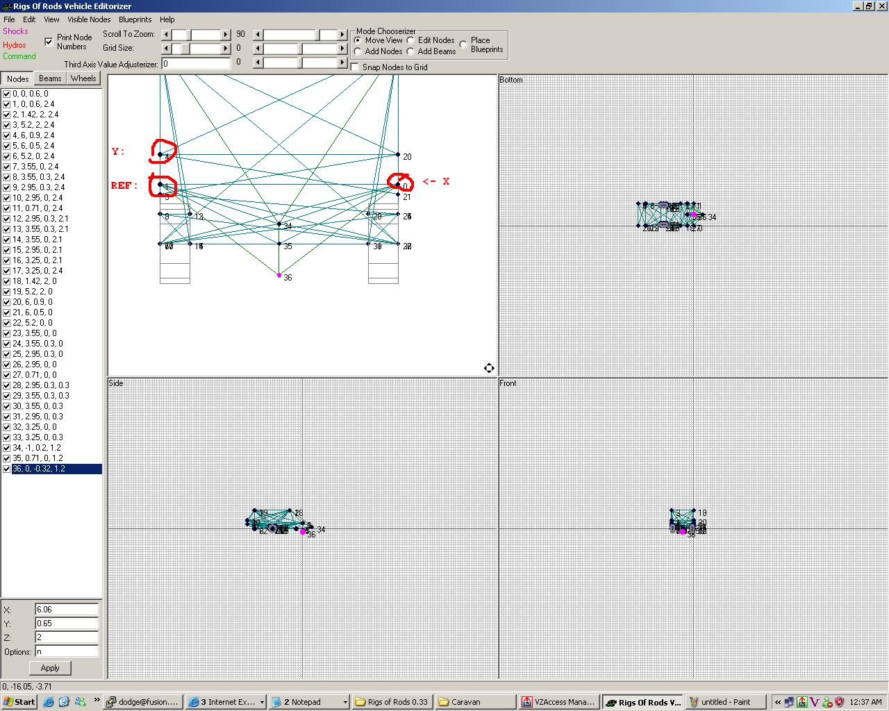
Before we begin, you'll absolutely need a truck editor, such as the Editorizer.
This will allow you to see where each node is placed in relationship to the coordinate plane (X,Y,Z).
Once the editor is running, and is open to the truck of your choice (It's suggested hat one starts out with something simple, such as the old Cartrailer.load, which can be found on the Repository)
You'll need to select the checkbox up at the top that says, Print Node Numbers This is pretty self-explanatory, as you'll need three node numbers later on to add your flares.
This next step can be challenging, depending on how many nodes and beams are present on the selected vehicle. You'll need to find three nodes close to where you want them on the vehicle. If you're adding brake/turn/head lights, it's suggested that you start with the lower lefthand corner of the front or back chassis, writing that node number on a piece of paper (this'll be your reference or REF node), then write down the node directly above it (this'll be your Y), and then finally, write the number of the node directly to the right of it (this'll be your X).
If you cannot find REF,X,Y nodes because they aren't where you want the lights (e.g. you're working on the school bus, which has the tail lights quite a bit above the bumper), you can add three nodes, in the same fashion as noted above, and use them to base your flares off of, but that's too advanced to go in this tutorial.
Getting to Know Notepad
Next up is man's best friend--the Windows notepad. If you're using another operating system, and/or another editor, that's fine, as long as it can save in ANSI format--it'll save you problems later on. Whatever you do, do not use MS Word/Wordpad/OpenOffice/AbiWord etc.
You'll need to open up the vehicle or load of choice with the aforementioned application (notepad or compliant editor). Here, you'll need to add a flare section
Once the line "flares" is added, you'll need to hit enter once, starting a new section, where it's advised you paste the syntax:
flares
;RefNode,X,Y,OffsetX,OffsetY, Type, ControlNumber, BlinkDelay, size MaterialName
Tutorial
So imagine a flat plane with 4 nodes, the direction of the planes face up, down, left or right determines where your flare will be.
There are two ways to do this.
First way:
flares
219,218,220,0.0,0.0,f,-1,0,0.50, default
The first node (219) is where the flare comes from and the other 2 (218, 220) determine whether it faces front or back of the plane.
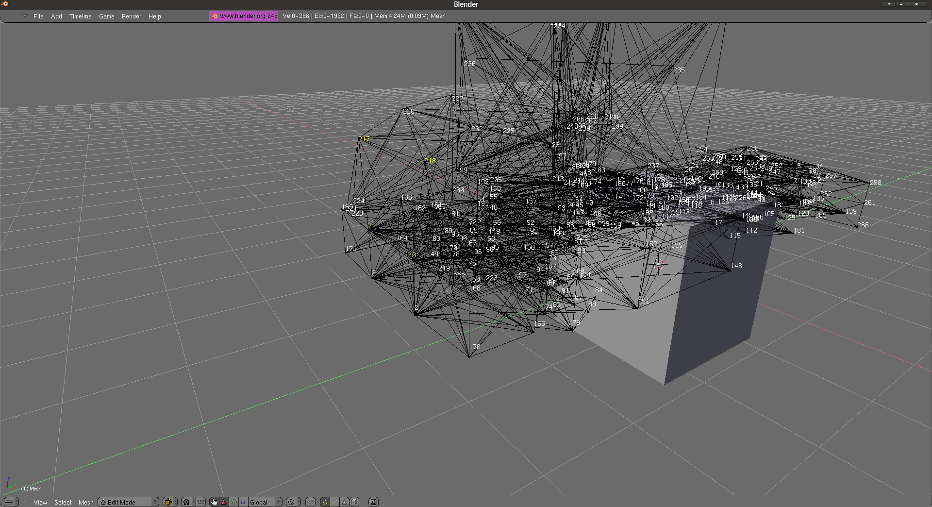
The 1st image shows my plane nodes 0, 1, 217, 218
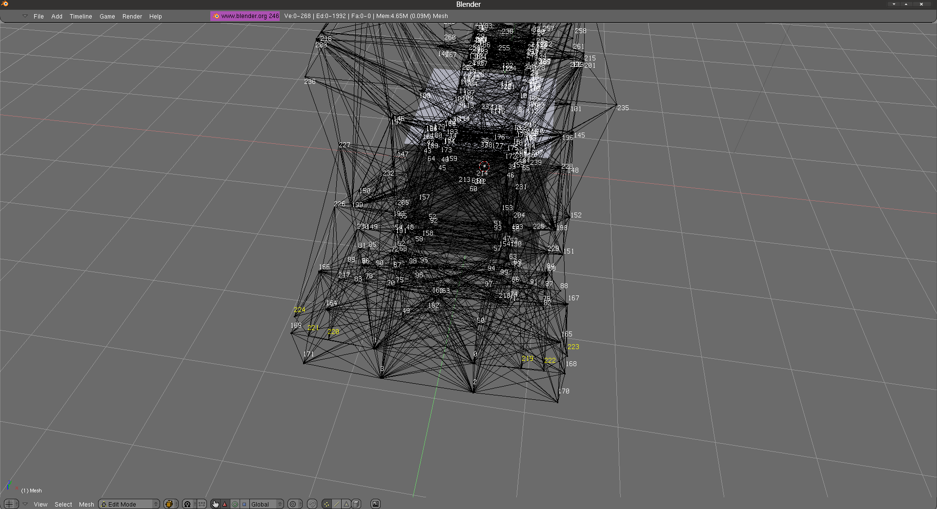
The 2nd image shows the nodes where my flares are going to be placed (optional to have them or not, just there to make things more precise and save time).
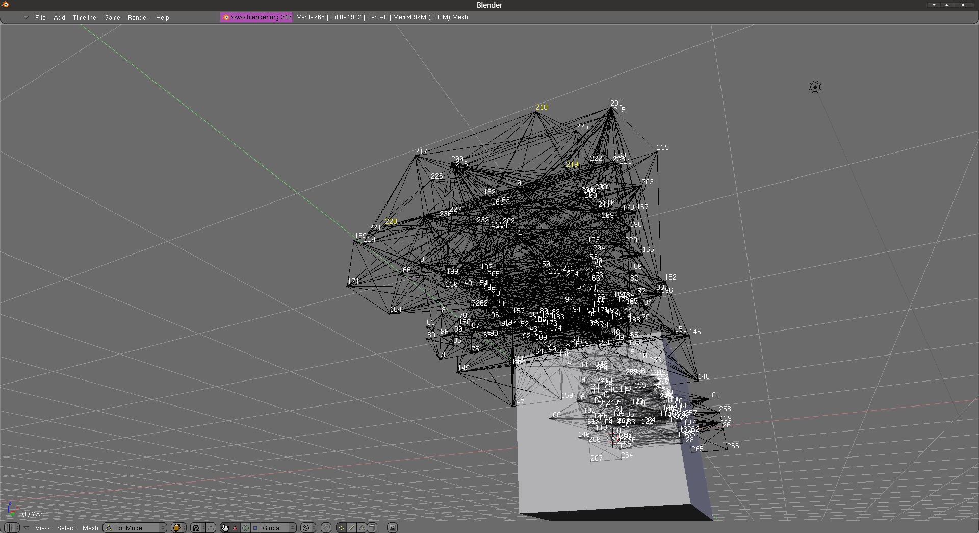
The 3rd image shows the placement for the left headlight, the first node 219 is where the flare comes from and 217, 218 makes it face frontwards, if I did 218, 217 the flare would face the other way.
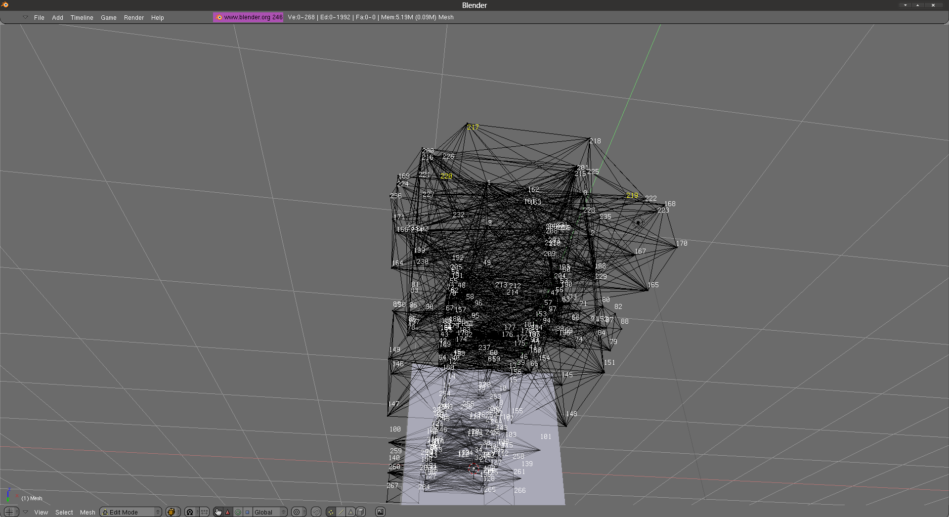
The 4th image shows the placement for the right headlight, the first node 220 is where the flare comes from and 219,217 makes it face frontwards.
To do the rest of the headlight flares, all I change is the first node, but keep the other two nodes depending on the side you want it.
The other way to do it is without the nodes where the headlights would be (you need to move the flare with the the red marked numbers).
219,218,220,0.0,0.0,f,-1,0,0.50, default
All you would do it replace the first node, so instead of 219, it would be 0 and then you would move the flare to the left.
flares
219,218,220,0.0,0.0,f,-1,0,0.50, default


flares
0,218,220,0.0,0.0,f,-1,0,0.50, default
Same thing apply for rear lights, top lights, side lights, just needs to have a plane, doesn't matter how big or how small the plane is since you can move the flare with the red marked numbers.
Syntax
Borrowed from Truck file format:
- Reference node: Node ID; Node which defines origin of flare-placement coordinate system
- X axis node: Node ID; Node which defines X-axis of flare-placement coordinate system
- Y axis node: Node ID; Node which defines Y-axis of flare-placement coordinate system
- Flare X offset: Real number; Flare position on X axis in % of distance from ref-node to X-node
- Flare Y offset: Real number; Flare position on Y axis in % of distance from ref-node to Y-node
This defines where the light flares will be. It is positioned in relation to 3 nodes of the chassis. One node is the reference node, and the two others define a base (x,y).
So the flare is in the plane defined by the 3 nodes, and is placed relative to the reference node by adding a fraction of the vectors ref-x and ref-y.
The three first parameters are the 3 nodes numbers (ref,x,y) and the two next gives what amount of ref-x and ref-y to add to displace the flare point (these two should be logically between 0 and 1, or else that means you use the wrong base triangle and if the body flexes too much the flare will not stick to the body correctly).
Basically, OffsetX/Y means that a fraction of X and Y will be added to the Reference node, which should be a corner, with a Y node above it, and an X node to the right or left of it. It's a bit easier, however, if it's in a left corner, than a right.
Example (* = node, + = flare location):
*
  +
*   *
Hint: Use the material name tracks/aimflare for help in positioning a flare.
Alright, back on topic: below the syntax, you should begin listing your nodes, keeping in mind their location on the vehicle, and the coordinate plane. You'll probably need to save, open up RoR, and test out the flares quite a few times before the placement of the flare is perfect.
Adding Symmetrical Flares
Okay, so you finally have that headlight, taillight, marker light, whatever-light in place. Now, you need one for the opposite side. Never fear, however, because there's a quite simple way of figuring out how to exactly place the other side's flare. Remember above, when it was stated, "these two should be logically between 0 and 1" about offset-X and offset-Y?
Well, anyway, once you have the first flare placed, just use that same exact placement line again, but this time, subtract whatever offset-X you used on the first flare from 1.0. Example: say we placed this headlight:
flares
;RefNode,X,Y,OffsetX,OffsetY, Type, ControlNumber, BlinkDelay, size MaterialName
0,10,1,0.345,0.55,f
That'd be the left side. To get the right side, we'd have to take 0.345 and subtract it from 1.0 to get 0.655. Then, we use 0.655 for the right side's offset-X. Since we want the right side flare to be at the same height as the left side, we use the same offset-Y. So, in turn, it'd look like this:
flares
;RefNode,X,Y,OffsetX,OffsetY, Type, ControlNumber, BlinkDelay, size MaterialName
0,10,1,0.345,0.55,f
0,10,1,0.655,0.55,f
This guide uses headlamps as an example, but this technique can be used to place any type of flare.
Troubleshooting Flares
Should the flare seem to stick to the interior of the vehicle when you select REF, X and Y nodes from the left side of the chassis, just use three nodes directly opposite on the right side of the chassis instead. This should thereby make the flare stick to the outside of the vehicle.
If you had to add nodes to a vehicle to place flares, and the flares seem to swing around or fall to the ground, ensure that you tied the said nodes into the frame of the vehicle with beams.
If a flare isn't illuminating when you attempt to turn it on, verify that the syntax is correct; the flare line has the correct REF, X & Y nodes; that it is of the correct type; and that the control number (if it's a user-controlled light) is correct. The flare could be showing up inside the vehicle, check the wireframe (hit K). If this is the case, see above.
Custom flares
Some times, default flares get a little boring, because there are not enough flash patterns or not enough colors. In this tutorial, you will learn how to make your own flare texture and your own flash patterns.
If you want to make your own custom flare textures, you will need a decent photo-editing program.
Making your flare texture
(You only need this step if you want to make your own flare texture/color. If you will use default flares, skip to step 3)
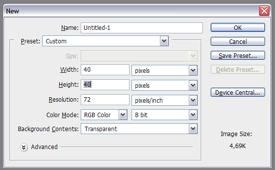
Open up a new document in your photo-editing software. Make the background transparent, and make it 40 pixels wide and 40 pixels high.
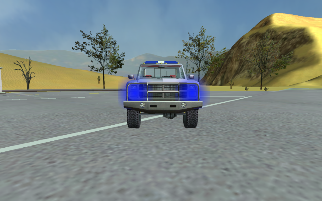
Right after that, pick a color for your flare. I will do blue, because I want blue flashers on my vehicle. So I will select the gradient tool and make a small light effect. (Note I zoomed in a little bit)
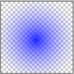
Remember to save your textures as Portable Network Graphics (PNG)
Then, save it as a name you will remember, such as Flare1 or Flash1.
For this tutorial, I will go with Flash1. Following that step, you must make another light effect, but 100% transparent. So create a new file in Photoshop with the dimensions and settings above, then simply save it as Flash2. This is needed because there needs to be an invisible flash when the light is off/deactivated.
Once you have saved the flashes, put them into the vehicle's .zip file you will be editing.
The Material file and the Material code
Locate the .material file in your vehicles .ZIP folder and open it with notepad. You will need to copy and paste the following code below...
material tracks/<a name for your new flare>
{
    receive_shadows off
    technique
    {
        pass
        {
            lighting off
            scene_blend alpha_blend
            alpha_rejection greater 2
            depth_write off
            //depth_check off

            texture_unit
            {
                anim_texture <the on image> <the off image> <animation length>
            }
        }
    }
}
(Thanks to Turbocharger for providing the code)
... Anyways, paste that to the bottom of your .material file of your vehicle.
If you inspect the code provided, you will see inserts where to put names.
For example, where it says <A name for your new flare> will be the name of your custom flare.
I would call it the same as my texture name, Flash1.
Then where it says <on image> and <off image>, put what it says.
For the on, put Flash1.png and for the off, put Flash2.png
And for animation length, put how long you want them to flash.
I would test values before I got it perfect.
After filling in the missing spaces, your .material code should look like this:
material tracks/Flash1
{
    receive_shadows off
    technique
    {
        pass
        {
            lighting off
            scene_blend alpha_blend
            alpha_rejection greater 2
            depth_write off
            //depth_check off

            texture_unit
            {
                anim_texture Flash1.png Flash2.png .5
            }
        }
    }
}
Save your .material file after completing this.
Editing the truck file
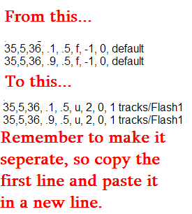
Open the .truck file, and find the flares section. To test these flashes, I would use the headlights as an example. So copy the headlight codes, and paste them below. You may have to change them from headlights, to custom flares. So if you see this in the headlight line: f, -1, you need to change that to: u, 1 because that makes it a user controlled flare (A flare you activate by pressing Ctrl+1) Then, instead of end of the headlight code saying default, change it to: tracks/Flash1 so it flashes your custom flare pattern.
Once you test it in game, it is a simple on/off flashing pattern.
Lets go one step further
Now that you can easily make an off/on flashing pattern, let's get more complex.
Get back into the .material file, copy the custom flare section, and paste it below. Now switch/reverse the
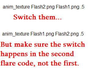
Now, open up the .truck file, and look at only ONE of the new flashing headlights, and change it's material name to tracks/Flash2.
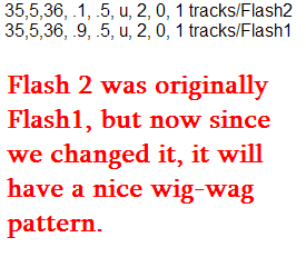
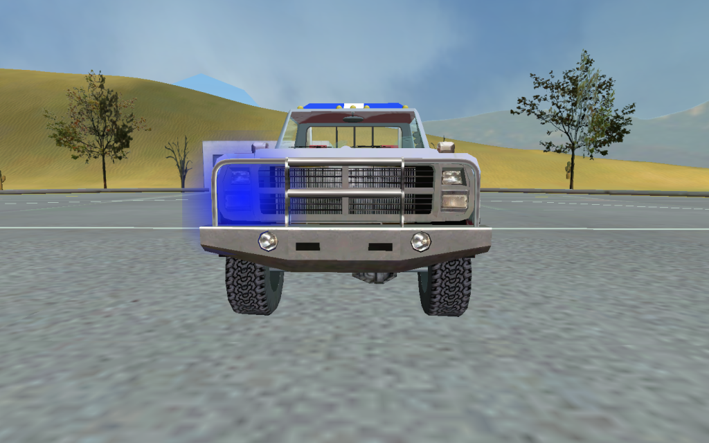
Now, see it ingame, it will be a wig-wag pattern.
Easy as that. There is a rule when it comes to making custom flashes:
When Flash1 is on, Flash2 is off. When Flash1 is off, Flash2 is on.
You can make a traffic advisor using this rule, or strobes, or anything you like.
Just refer to this tutorial and be creative.