Suspension
Suspension is a flexible component which connects a car's body to its wheels. because of its flexibility, suspension components soften out bumps in the road and make the truck's ride smoother.
For syntax, see truckfile reference.
Example trucks
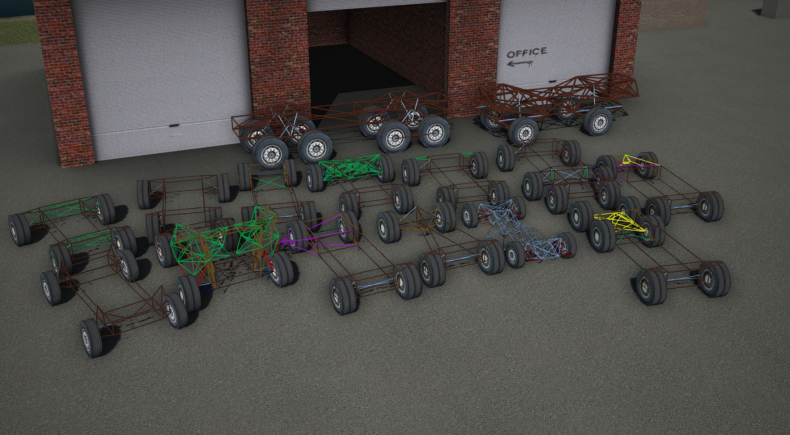
A package containing all example trucks featured can be downloaded here.
Types
Coilovers
Coilover springs (standing for 'coil-over-oil') are extremely simple to model in RoR, since the game's shocks simulate them directly.
Things to keep in mind:
- Spring is the measure of resistance change to the shock's of position, or how 'stiff' the suspension is. The shorter or longer a shock is compared to its original length, the more force it will exert to try to get back to its original length.
- Damping is a measure of how fast the shocks can change their length: the faster a shock tries to change its length (by compression or extension of the suspension), the more resistance the shock will apply. Too little damping will make the suspension too bouncy. Too much damping and the suspension will not be able to move well enough in response to bumps.
So, for soft suspension you would want low spring and relatively low damp, and the opposite for stiff suspension (high spring and relatively high damp). Shocks behave differently based on the force acted upon them. So a shock that is good for a truck weighing several tonnes will be much too 'stiff' for the same shock on a street car.
Leaf springs
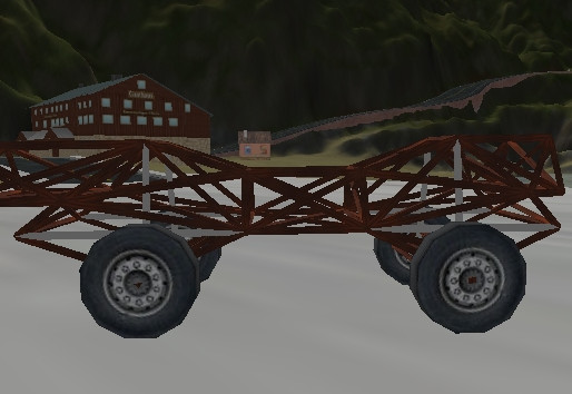
Leaf spring suspension is a very simple (in real life; it is much harder to model in RoR) and efficient design found on almost all trucks using beam axles. The design consists of a spring and a shackle, the spring is a long metal arc that bend when a force is exerted on the spring. One end of the spring is securely mounted to the frame and the other to a shackle. The shackle allows for one end of the spring to move back and forth as the spring straightens out under force.
Dependent suspension
The wheels of each axle are securely connected to each other using non independent suspension systems. The force from every bump that a wheel on one side goes over is transmitted into the other wheel too. These systems do not tend produce very good handling, and therefore are not often used on sports cars. Non independent suspension is much more commonly found on heavy duty vehicles, where the link between the wheels makes axles much stronger
Beam axle
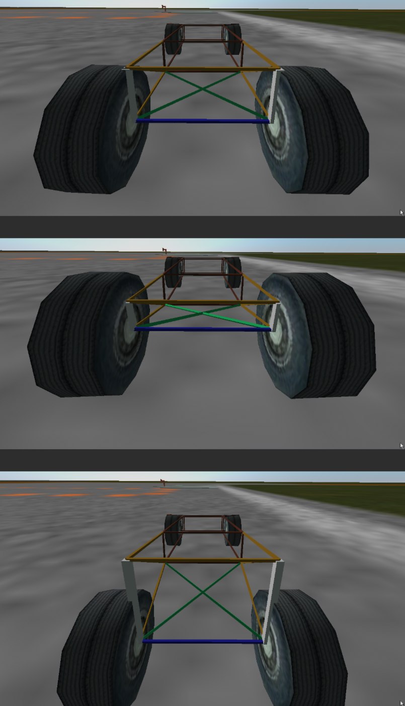
Beam axles are an extremely simple form of suspension, almost always seen on the back axles of vans and semi trailers. The wheels are directly attached to the axles, and cannot change their angle to it.
The easiest way to create a beam axle is to use Axle Rigidity nodes.
The lateral location of a beam axle can be controlled in a number of ways; the easiest way in RoR simply to weakly truss the two arms that hold the axle, but this is generally not possible in real life and limits how much the axle can roll.
Example using a beam axle on the rear, with simple truss for lateral location.
- Top image: Normal extension
- Middle image: Full compression
- Bottom image: Full extension.
- Blue: Axle.
- light brown: Frame and trailing arms.
- Green: Simple truss for lateral location
Watt's linkage
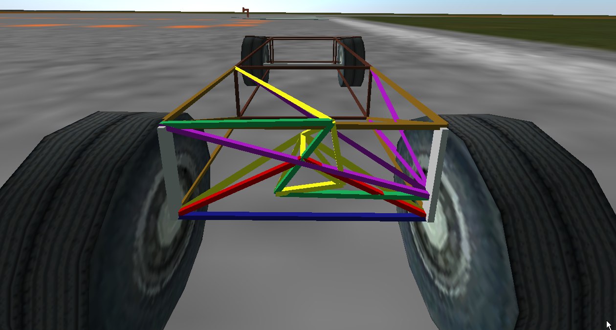
Example using Watt's linkage method of lateral location.
Watt's Linkage:
- Blue: Axle.
- Light brown: Frame and trailing arms.
- Purple: Holder for Watt's Linkage
- Green: Watt's linkage (the 2d elements of it).
- Yellow: Trusses and A-arms to hold linkage in place
- Red: Connector for Watt's linkage and axle
Panhard rod
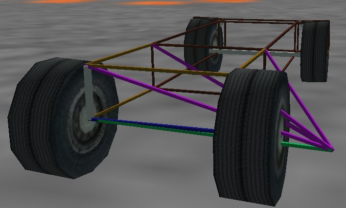
Panhard rod:
- Blue: Axle.
- Light brown: Frame and trailing arms.
- Green: Panhard rod.
- Purple: Holder for Panhard rod
De Dion tube
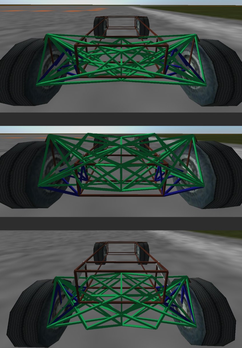
De Dion tube suspension is a relatively complex form of suspension, which falls in between the categories of independent and non independent suspension: The wheels are directly connected to each other using a sliding tube, forcing them to stay parallel to each other, but this tube is not connected to any other part of the vehicle. each wheel is actually held to the truck by a single A-arm
Due to their complexity, De Dion tubes are uncommon on modern vehicles.
Example using a de Dion tube on the rear. Since a telescoping tube cannot be directly modeled in RoR, a Sarrus Linkage has been used instead. It provides exactly the same effect.
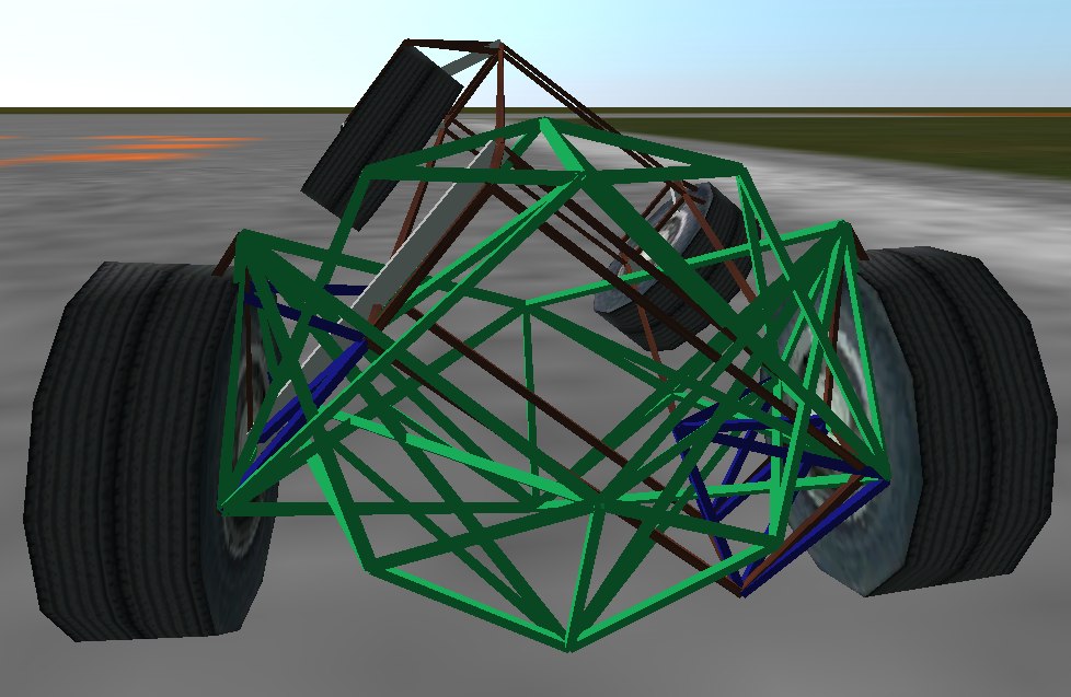
The wheels connected to the tube are kept parallel, regardless of body roll or suspension travel on either side... The tube's length can change.
- Top image: Normal extension
- Middle image: Full compression
- Bottom image : Full extension
- Blue: A-arms.
- Green: De Deion Tube
Walking beam
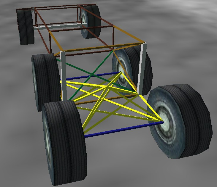
Walking beam is a special form of suspension: It solidly links two axles together, meaning that all four wheels on those axles must move in unison. Indeed, the setup is know as walking beam due to the way that trucks are see to 'walk' over obstacles. This design allows the tires to conform to the landscape, evening out the pressure on each tire.
Example using extremely simple walking beam suspension on the rear.
- Blue: Axles.
- Light brown: Frame and trailing arms
- Green: simple truss for lateral location.
- Yellow: Frame for walking beam
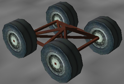
The bogie that holds the truck's four back wheels together.
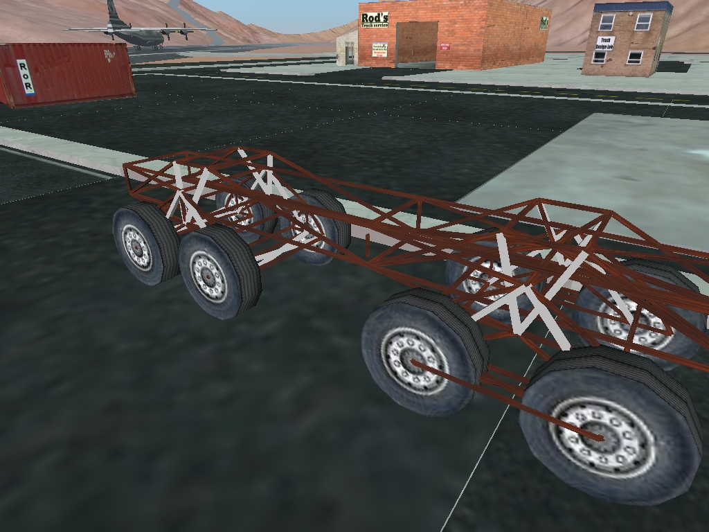
A concept vehicle in game.
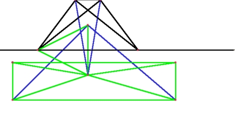
- Black: Structural beams
- Green: The suspension
- Blue: Shocks
Independent suspension
There are no significant connections between wheels in independent suspension setups. They are therefore much more suited to vehicles where roadholding is especially important.
Swing axle
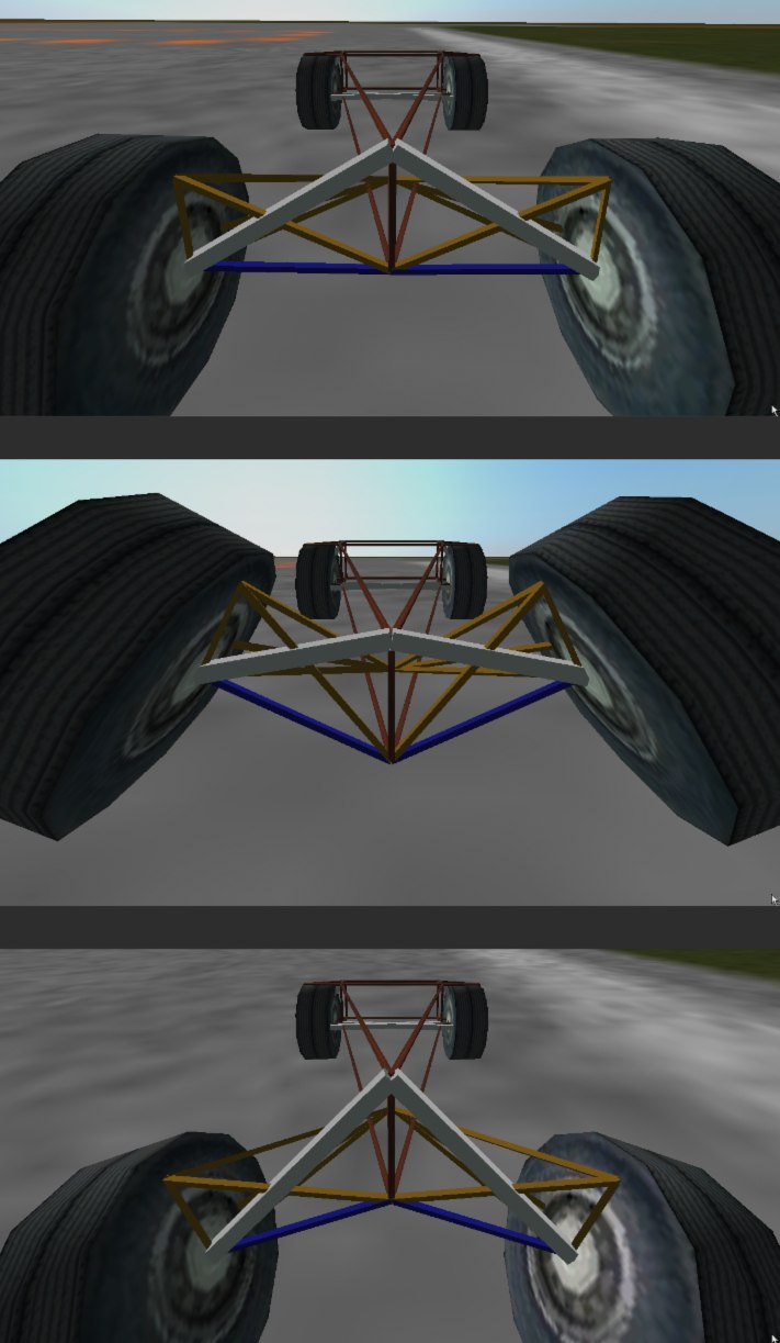
The swing axle is a small step up from the beam axle. Although it is the most common form of suspension on Pricorde's trucks, it probably produces the worst handling vehicles in the game, due to the way the camber changes when going over bumps.
Because of its strange handling characteristics, swing axle suspension is uncommon in modern trucks.
Example using swing axles on the rear. The axles on this truck are quite short, which encourages the inside wheel to tuck under when cornering.
- Top image: Normal extension
- Middle image: Full compression
- Bottom image: Full extension
- Blue: Axles.
- Light brown: trusses and A-arm for axles.
Double wishbone
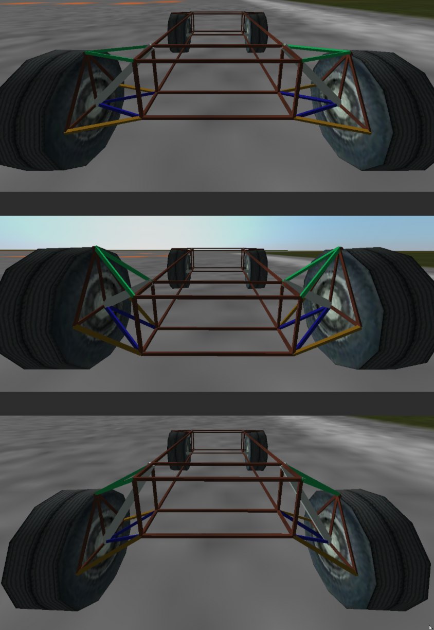
Double wishbone suspension is most common in racing cars and larger passenger cars. The wheels are kept perpendicular to the road through the use of two A-arms, one above the other. It is relatively easy to tune for handling.
Example using double wishbone suspension on the rear. The front axles also carry double wishbone suspension and are used for steering. The front wheels have also been rotated to place them inside the wishbones, which makes them much stronger; any object they collide with exerts less leverage on them.
- Top image: Normal extension,
- Middle image: Full compression,
- Bottom image: Full extension
- Green: Upper wishbones
- Blue: Lower wishbones
- Light brown: Extra truss arms.
Hydros could go here when modelling steering axles
McPherson strut
By far and away the most common form of front suspension for passenger cars, the spring/shock assembly must not only provide suspension to the wheel, but hold it in place, keeping the wheel aligned to the shock at all times. This requires the use of some sort of straight line mechanism with the shock
Example 1
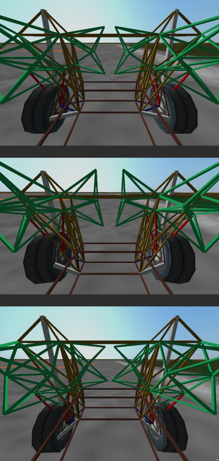
Old-style example using McPherson strut suspension on the front. The straight line mechanism has been hidden on the right hand side to provide a better view of the overall setup.
- Top: Normal extension
- Middle: Full compression
- Bottom: Full extension
- Blue: A-arms.
- Light brown: holder for straight line mechanism and shock
- Green: Straight line mechanism,
to keep the shock and the wheel holder pointing in the same line. - Red: connector from the straight line mechanism
to the bottom of the wheel holder
Example 2
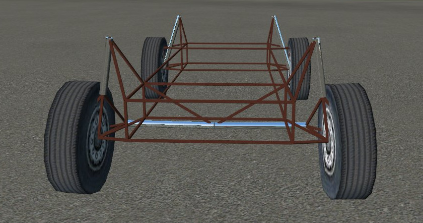
An example truck using slidenodes to keep the beam count down. No beams in the suspension mechanism have been hidden, the shocks are hold in line with slidenodes.
Torsion bar
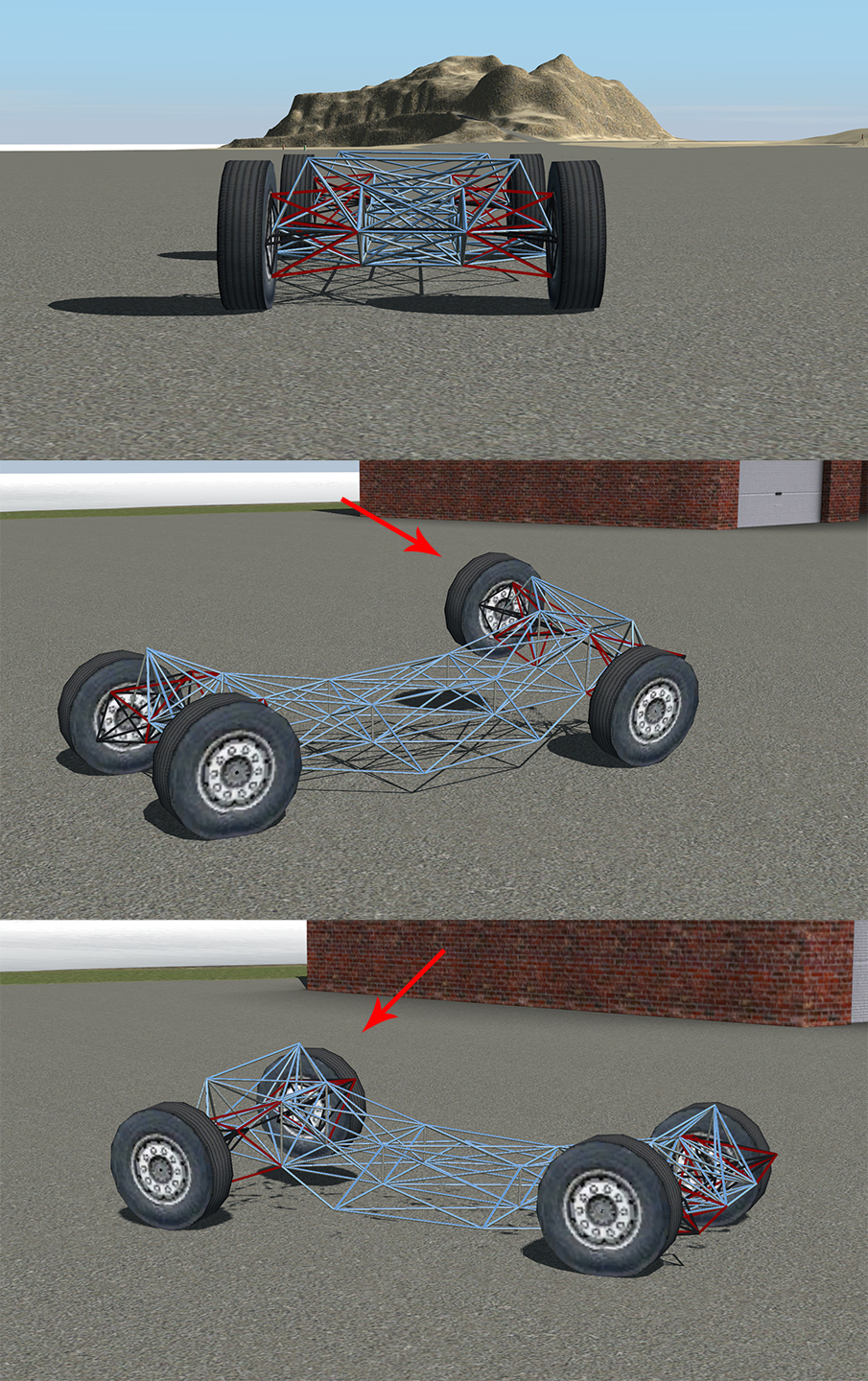
A torsion bar is a simple form of independent suspension that uses a flexible rod to provide spring force instead of a coil spring. It can be found on many vehicles from the VW beetle, to light trucks and SUVs, or even trailers.
Example using torsion bar suspension front and rear. You will notice the wheels tend to gain camber while cornering like swing arm suspension, however since the pivot point is perpendicular to the wheels, they will not fold under the chassis like a swing arm.
- Top image: Normal extension
- Middle image: Full compression
- Bottom image: Full extension
- Grey: Axles.
- Red: Torsion bar beams.
Other forms of independent suspension
- Twin Traction Beam - A beam that goes to the other side of the truck where it is connected to the chassis.
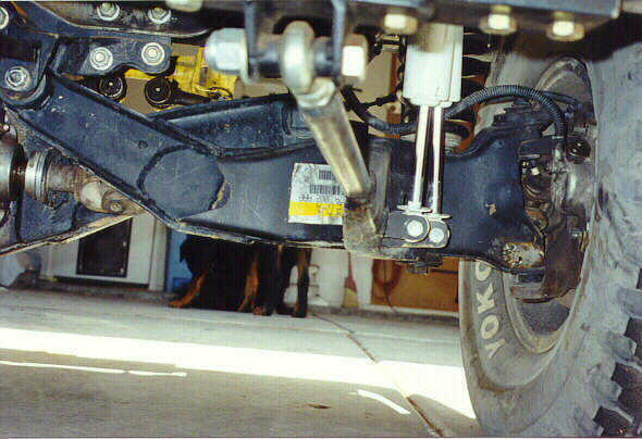
- Multilink - Multilink, or 5-link, system are called so because they use 5 different points to connect the fusee to the chassis.
- Trailing-arm - Two arms that look like the 4 link system except that there is not solid axle.
Special parts
Anti roll bars
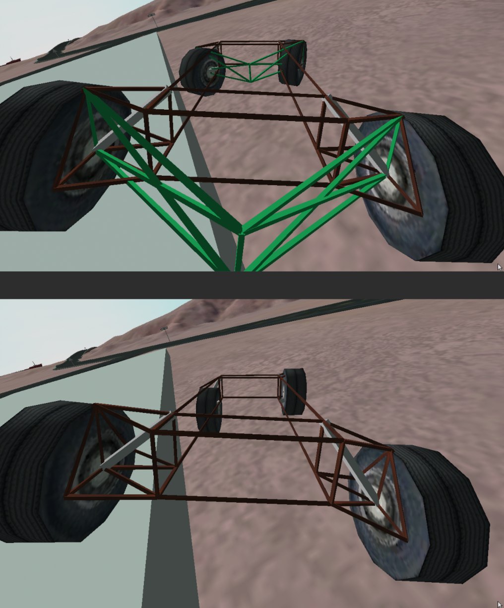
Anti roll bars are stiff beams which run across vehicle axles to lessen body roll when cornering. This makes vehicles hold the road much better when cornering.
Top:Truck with anti roll bars. Bottom: Truck without anti roll bars. Notice how the front wheels are much farther apart in the top image. Green: Anti roll bar.
The setup of anti roll bars differs slightly depending on the type of suspension they are being fitted to. In all cases, they must pivot on the truck body itself, but with suspension setups that use transverse A-arms, such as double-wishbone or swing arm, care must be taken to allow for left-right movement in each wheel. If this is not done the suspension will lock up during travel.
The two trucks here are identical except the second truck does not have an anti roll device fitted. The anti roll device shown is suitable for any truck which uses same length double wishbone suspension.
Examples with and without the anti roll bars are included in the main download.
Liftable Axles
Liftable axles have been implemented in a couple of ways in RoR.
Example 1
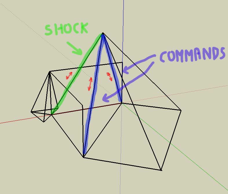
Creating a basic liftable axle is as easy as replacing part of the supporting beams with commands. Note that if your commands are too long/too short, your shocks will break. In the picture above, the commands lift the node that the shock is attached to, effectively moving the axle.
Example 2
Another way of accomplishing this same concept without stressing the axles is to lift the shocks, instead of the wheel.
The commands will lift the shock and, consequently, the wheel will travel with the shock thus lifting the axle without stressing the shocks. This allows you to have very stiff shocks without fear of breaking.
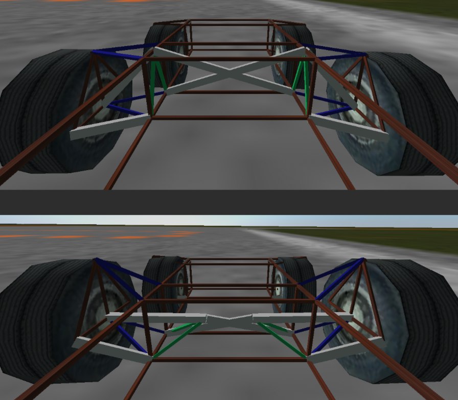
- Top image: Axle lowered.
- Bottom image: Axle raised.
- Blue: A-arms.
- Green: A arm to connect shocks and commands (Shocks are on outside, commands on inside).