Wheels, axles, steering
Wheels
wheels are simply structures that the game creates automatically out of standard features to make creating vehicles easier. They are simply nodes connected by beams with a contactable submesh. They are unique in that they will rotate when given input to accelerate.
Wheels are the most basic wheels in the game. The width of a wheel is determined by the distance between the two reference nodes and is composed of pie slices known as rays. The more rays a wheel has, the smoother it will be but will also contain more nodes and beams and consequently lower performance. It is considered good form to keep your rays between 10 and 20.
The optional snode option allows for game-managed Axle Rigidity. This will keep the two wheel reference nodes in line under normal conditions. If snode is NOT used, you must enter 9999.
wheels
;radius, width, numrays, node1, node2, snode, braked, propulsed, arm, mass,  spring,   damping,   facemat          bandmat
0.54,   1,  12,       1,     2,   9999,    1,      1,         25,  400.0, 800000.0, 4000.0, tracks/wheelface tracks/wheelband2
0.54,   1,  12,       3,     4,   9999,    1,      1,         23,  400.0, 800000.0, 4000.0, tracks/wheelface tracks/wheelband2
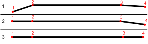
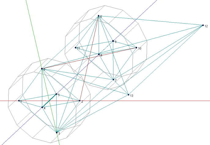
First step: The snode is Disabled ( The data is 9999), the nodes 1 and 4 are hanging just down.
wheels
;radius, width, numrays, node1, node2, snode, braked, propulsed, arm, mass,  spring,   damping,   facemat          bandmat
0.54,   1,  12,       1,     2,      3,    1,      1,         25,  400.0, 800000.0, 4000.0, tracks/wheelface tracks/wheelband2
0.54,   1,  12,       3,     4,   9999,    1,      1,         23,  400.0, 800000.0, 4000.0, tracks/wheelface tracks/wheelband2
Second step: You type 3 to the snode option of the wheel 1,2. Now node 1 will always have the ambition to be at the same "line" like the nodes 2 and 3.
wheels
;radius, width, numrays, node1, node2, snode, braked, propulsed, arm, mass,  spring,   damping,   facemat          bandmat
0.54,   1,  12,       1,     2,      3,    1,      1,         25,  400.0, 800000.0, 4000.0, tracks/wheelface tracks/wheelband2
0.54,   1,  12,       3,     4,      2,    1,      1,         23,  400.0, 800000.0, 4000.0, tracks/wheelface tracks/wheelband2
Third step: You type 2 to the snode option of the wheel 3,4.
Now all nodes will be on one level / line even node 1 and 4 aren't mounted primary to the chassis.
Wheels2
This feature improves the default wheels section by splitting wheels into rims and tires. This allows the player to set tire pressure with the keyboard.
Wheels2 (also known as the "complex wheel model") allows you to separate the wheel [rim] from the tire (tyre). This requires extra syntax, namely specifying the characteristics of the wheel versus the tire. Traditionally the wheel will be very rigid with the tire being much less so. The rigidity of wheels2 tires can be altered by holding [ and ] ingame, resulting in this:
| Inflated tire | Deflated tire |
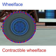 | 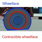 |
The adjustable tire pressure allows you to adjust handling in real-time. Lower pressure creates more grip while higher pressure creates more stability.
Meshwheels
Meshwheels takes advantage of a mesh's static nature. It also creates a smoother tire. The wheel rim is a standard Ogre3D mesh.
Meshwheels are very similar to normal wheels, but require specification of the wheel rim radius. Likewise, the direction the wheel is facing must be specified in order for the mesh to be rotated properly.1
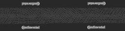
| Here is an example picture of a rim mesh, as it should be modeled. The actual tire will be added dynamically and will still flex. | This material should be slightly different to other tire materials as it covers both the tire face and the tire wall: |
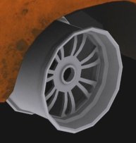 |  |
Notes
The mesh should be centered (Where should the wheel be placed in the L/R direction? Should it face left or right?) and of the right size for the wheel you want to do: its outer diameter should be as the rim_radius parameter, and its width should be the same as the distance between node1 and node2. All wheels are able to do skid steering. See the steering chapter.
It is considered good form to keep your rays between 10 and 20.
Axles
This section defines axles on a vehicle, allowing more accurate distribution of torque among the wheels.
Sample axle section:
axles
; axle 1
w1(1 2), w2(3 4), d(ol)
; axle 2
w1(5 6), w2(7 8), d(l)
The axle section introduces open differentials, and Spooled (aka locked) differentials. By adding axles to your vehicle file you override the propulsed property for the tires. Only wheels connected to an axle are powered, if multiple axles are defined the axles are interconnected in a locked manner. If no axle section is defined the old model of equal power distribution is used. Because the axle sections looks up already defined wheels, it must be defined AFTER the wheels have been defined
The axle section if different from other sections in that it is broken into properties, properties are not order dependent, currently the available properties are:
- w1(<node1> <node2>) - this defines which wheel the axle is attached to, <node1> and <node2> refer to the node1 and node2 as defined in the wheel section
- w2(<node1> <node2>) - wheel 2, same as w1, this is the second wheel attached to the axle. w1 and w2 are interchangeable.
- d(<list of diff types>) - Defines the available differential types for this axle. the list of axles is cycled through in the order specified, differential types maybe specified more than once. Each differential type is specified by a single letter, the letters are not to be separated by spaces or any other character. if no differentials are specified the axles will default to opened and locked.
- Available differential types
- o - open
- l - locked
- s - Split evenly (each wheel gets equal torque regardless of wheel speed)
- Available differential types
Problems?
Wheel weight has a big effect on top speed since heavy wheels have lots of rolling resistance in RoR. Try to make the wheels as light as possible. If the wheels explode, they probably have too high damping for the weight. If the wheels and rpm needle start shaking, set lower clutch torque in the engoption section. This can take some tweaking, but it's worth it.
Used together with fusedrag and realistic truck weight, real torque is often enough so there's no need to have several thousand hp engines. That makes the trucks easier to drive and better handling.
Axle Rigidity
See Also: Suspension
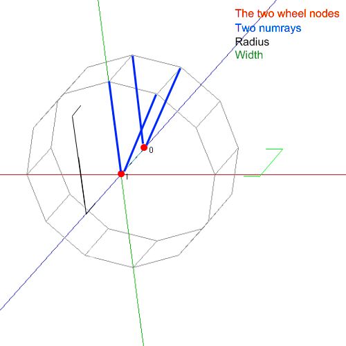
The Axle Rigidity keeps the wheel aligned with the axle of the vehicle. It is used to avoid having to make a complex structure in order to hold the wheel in place. In fact, it keeps the two wheel nodes and the defined node in a straight line. This is intended to use with solid non-steerable axles. However, you probably can devise a way to use this as independent suspension.
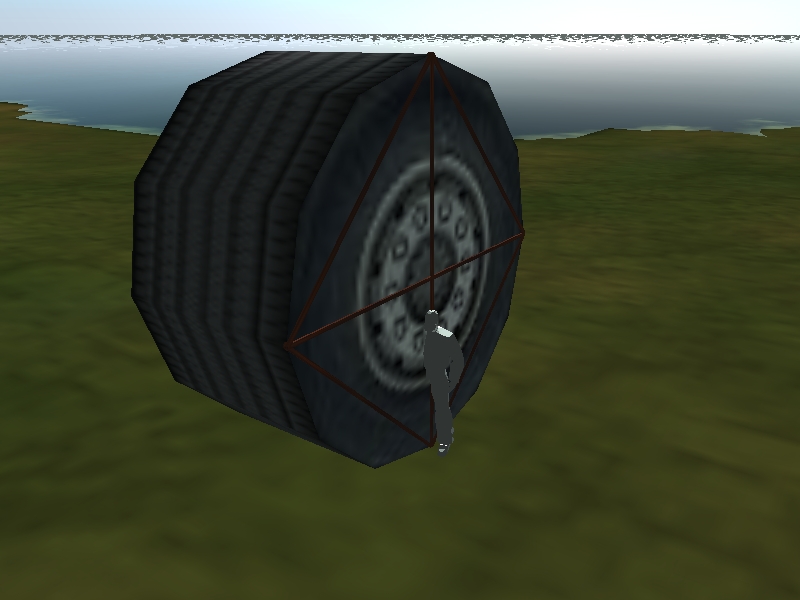
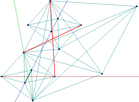
Normally a wheel needs some sort of pyramidal hub to support it, such as the image to the right. Axle rigidity allows you to avoid making this by doing some internal magic to keep the nodes supported. Wheels need at least 2 nodes to define their width, and the node used for axle rigidity is the innermost node of the wheel.
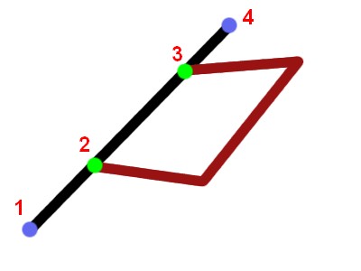
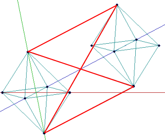
Here, the black beam are normal beams. Red beams are a crude suspension set up. Light-blue nodes are the outermost wheel nodes, while green nodes are axle rigidity nodes.
For the left wheel (defined by nodes 1 and 2), the special rigidity node will be 3, and for the right wheel (defined by nodes 3 and 4), the special rigidity node will be 2.
Reference Arm Node
This is to help modders, as I have seen a few asking about what this does.
What it does
The reference arm node in the .truck file serves an important purpose. That purpose is to determine where the torque reaction in a chassis will be. If that node is placed in front of the specified wheel, then it will provide more traction, as the wheel pushes the chassis down into the ground. This is good for vehicles such as off-roaders and high-grip racecars. If the arm node is behind the specified wheel, then grip will be reduced as the wheel will help lift the chassis off the ground. This is useful for drifters and other cars and trucks that need less grip.
How it is Implemented
The arm node is implemented through the wheels section of a .truck file.
Example Vehicle
A good example vehicle that shows how the arm node works is box5diesel's Baja Trophy Truck. When in the air, if you accelerate in 6th gear, the nose of the truck will be lifted up. If you brake while in the air, the nose of the truck will be pushed down. This is due to the arm nodes of the rear wheels being located in front of the rear axle, and the arm nodes for the front wheels, located behind the front axle.
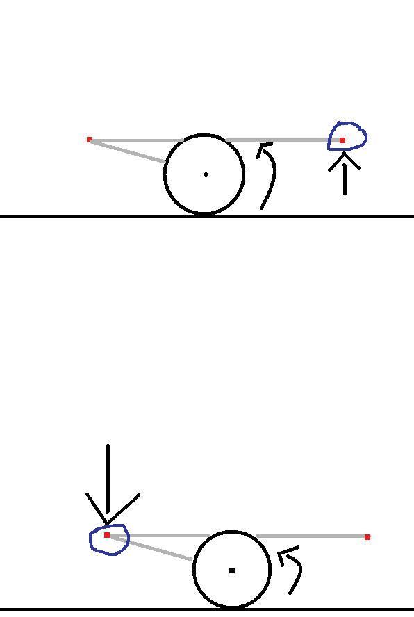
Example Diagram
This is a rough diagram I made to show how it works. In the top diagram, the arm node is behind the wheel, so as the wheel spins counterclockwise, it applies upward force to the node(red) in the blue circle, therefore imparting less traction as the chassis is pushed upward.In the bottom diagram, the arm node is in front of the wheel, so as the wheel spins counterclockwise, it applies downward force to the circled node, therefore imparting more traction as the chassis is pushed downward.
Steering
Steering is made possible with the use of hydros. A proven steering set up which involves a diamond wheel support and a small chassis which the suspension is attached to. When this concept is realized, steering is not too difficult.
Wheel Mount
This is a typical wheel support diamond ("face octahedron"). This will carry the wheel independently from the main chassis. For example:
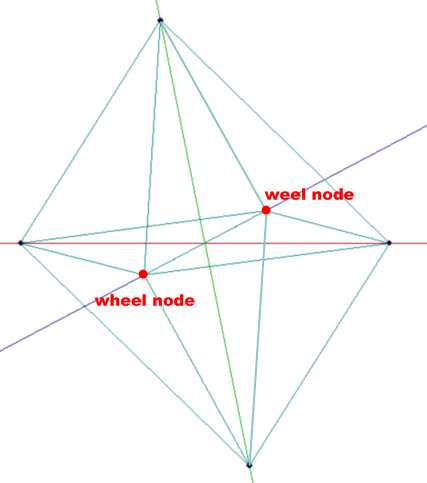
The "wheel" nodes labeled here will become the position for the wheels. The distance between the two nodes will determine the wheel width. It is wise to make the diamond symmetrical for stability (that is, the height equals the width). You will need one of these for every wheel that is steerable.
If you find your nodes are contacting the ground and obstructing movement, you can make specific nodes non-contactable. See the nodes syntax.
Axle
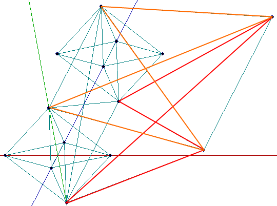
The axle is actually simply built out of four beams:
But you need a rocker, too. However it's easy to build. This only requires two nodes in front of the axle (be aware these nodes should be at least 80cm from the axle away) and beams attached to them as shown at this picture:
Hydros
After the steering chassis is completed, the hydros can be added. Hydros are simply beams that change length when you press the right and left arrow keys, and are typically used for steering (although you can use them for other purposes if you so wanted).
In order to define a hydro, some specific information is needed.
- Node 1 - One end of the hydro
- Node 2 - The other end of the hydro
- Factor - The decimal percentage (0.2 = 20%) representing how far a hydro can extend.
- The length of a hydro can be determined by Original Length ± (Original Length * Factor)
A hydro can also have two optional parameters:
- i - The Hydro will be invisible
- s - At approximately 20km/h to 40km/h the factor will be lowered gradually to 0 and will then be disabled. This is commonly used for rear-wheel turning, as it is disabled at high speed.
Example Syntax:
hydros
;node1, node2, factor, options
43,    37,    -0.2,   i
46,    36,     0.2,   s
The following example shows how hydros will push and pull nodes in a direction to induce steering:
Finished Steering Axle
The finished axle can look like this:
Don't forget to add suspension (as covered in the previous chapter)
Braked Steering
It is possible to have a steering system that only turns one side of wheels. In the wheels section, set the Wheel Braking value to 2 or 3 for left or right wheel respectively. This works well for emulating tracked vehicles such as bulldozers. These usually do not work well at high speed.